8
\$\begingroup\$

It's been a dream of mine to build an analogue synthesizer for a few years.

In this time I've built VCOs based on the 555 timer, which I know do not generally have an accurate frequency response without a lot of additional circuitry.

555 VCO

I've also built a VCO based on the LM358 op-amp. This seems to sound better and be more stable.

358 VCO

A lot of VCO designs I've found on the internet are quite complicated to build and require the +-12v power supply. Here's an example of one designed to run on two 9v batteries inverted.

358 V/Hz VCO

What I'm looking for is a simple design, not a huge amount of components, V/Octave frequency response and powerable by DC from a battery(or two) (with an audio frequency range somewhere between 20Hz-12.5kHz).

I'm also considering the DCO approach, the Juno method of using a programmable divider to attain a frequency from a master clock seems very attractive.

\$\endgroup\$
10
  • \$\begingroup\$ What frequency range? Mentioning 555 implies you're talking about kHz, not MHz, but you never say so. \$\endgroup\$
    – The Photon
    Commented Mar 17, 2013 at 15:01
  • \$\begingroup\$ audio frequency range. just edited the question to include this. \$\endgroup\$
    – blarg
    Commented Mar 17, 2013 at 15:04
  • \$\begingroup\$ 1V/octave implies an exponential relationship between voltage and frequency. Doing this in the analog domain usually involves a diode junction of some sort, and it takes quite a bit of care (and complexity) to make such a circuit both accurate and stable enough for music purposes. How would you feel about "simulating" this function with a single-chip microcontroller? \$\endgroup\$
    – Dave Tweed
    Commented Mar 17, 2013 at 15:29
  • 2
    \$\begingroup\$ 1V per octave with 20Hz to 15KHz range is a control voltage that is probably going to be a problem with a 9V battery. I'm not saying that you can't scale it down but i am saying this adds a little more complexity and you are looking for a simple design. The linearity of simple analogue VCOs are very poor too especially if they need to span 9+ octaves. I would consider digital approaches. \$\endgroup\$
    – Andy aka
    Commented Mar 17, 2013 at 17:10
  • 1
    \$\begingroup\$ @JackDamery - the new circuit you have added is still a linear Hz per volt circuit - you cannot use this for a VCO in a synthesizer - it has to be octave/volt. \$\endgroup\$
    – Andy aka
    Commented Mar 22, 2013 at 8:57

6 Answers 6

7
\$\begingroup\$

There are reasons why analog synths are largely obsolete today, and the main one is that making a good VCO that stays in tune over a wide range of voltages and temperatures is super difficult. I suggest an alternative, hybrid approach.

Use a simple microcontroller, either with the built in DAC or external audio DAC, as your "oscillator". The input to the MCU could be an analog voltage to the internal ADC, MIDI data, or some other digital data. The output would be a sine wave of the correct frequency. The output then goes to your analog circuitry of choice.

Be sure to run the MCU off of a real XTAL or quartz oscilator and not from the internal oscillator. The internal oscillator is not accurate enough to keep things in tune.

The cool thing about this approach is that you can easily output things other than sine waves. Square, triangle, sawtooth, or something "custom" is just as easy as a sine wave. This gives your analog filters more harmonics to play with and create more interesting and useful sounds. Oh, and it is fairly low power when compared to the typical ways to do VCOs.

The first "digital" synths in the 1980's used this hybrid approach and is really the main technological advancement that made synths have a wider market appeal-- at least until we have the processing power to do it entirely in the digital domain.

\$\endgroup\$
5
  • 2
    \$\begingroup\$ Thanks for this informative response. This approach is very attractive, perhaps I could get a similar sound to the Korg DW8000? I think the difficulty level, steep learning curve and unpredictability are part of the attraction of building an analogue synth. \$\endgroup\$
    – blarg
    Commented Mar 19, 2013 at 17:51
  • \$\begingroup\$ @JackDamery - if you go down this route, don't underestimate the precision of the ADC. 3 octave control from say 1V to 4V covers 36 semitones and if you want a "smooth" glissando effect you'll probably want to aim for 20 steps per semitone. At the low end of the spectrum, a semitone change would be a volts change of about 50mV and you will therefore need 2.5mV for the step of 1/20th a semitone. This implies an ADC resolution of about 11 bits and this is only for a three octave VCO. Go for 16 bit if you can. \$\endgroup\$
    – Andy aka
    Commented Mar 19, 2013 at 18:37
  • \$\begingroup\$ I've been investigating using this library for the Arduino as a waveform generator and then waveshaping/filtering using analogue circuitry. Really I would prefer to abstract the waveform generation from any microcontroller though. Am I to understand in your original response, you're suggesting using an analogue voltage in to vary the frequency of the digital oscillator to simulate analogue variation. \$\endgroup\$
    – blarg
    Commented Mar 21, 2013 at 17:31
  • \$\begingroup\$ @JackDamery You can use whatever means you want to control the MCU: MIDI, analog in, I2C, SPI, etc. That is completely up to you, and depends on what the rest of your system looks like. I, personally, would use a digital connection because I don't like to mess with the inaccuracies of analog signals, but analog could work too. \$\endgroup\$
    – user3624
    Commented Mar 21, 2013 at 18:53
  • \$\begingroup\$ Another approach I remember seeing on someone's plug-board synth (circa 1989) but never used personally was to use a microprocessor, DAC, and quad analog sample and hold ("quash") to produce control voltages for four linear-V/F oscillators. The processor could use a look-up table of pitches, eliminating the need for a precision exponential converter. \$\endgroup\$
    – supercat
    Commented May 16, 2016 at 19:23
4
\$\begingroup\$

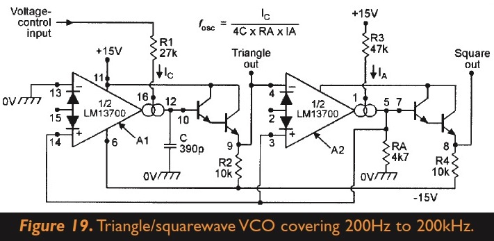
I've just successfully built a VCO. It produces square and triangle wave, can be controlled with voltage (LFO, sequencer, etc) and easy to build. Check out this article. The VCO is at page 10. Even though the schematics implies +-15V (30V) I only used 0-9V. The IC is an LM13700 OTA (operational transconductance amplifier). OTAs are widely used in analog synths since voltage control can be realised easily. An OTA is a kind of op amp with a few extra features. You can build a VCO, VCA and VCF using these ICs and in the Marston-article there are example schematics for all the three. OTA VCO from Ray Marston's article (Nuts&Volts)

\$\endgroup\$
1
  • \$\begingroup\$ Send me a message to alkopop79 at gmail dot com! I can elaborate more on the OTAs. I highly recommend reading Forest Mim's 'Op-amp IC circuits (Engineer's mini-notebook)' book. The LM13700 can be purchased cheap from Rapid Online in the UK (they're damn expensive on Ebay!). Using OTAs are not that easy but much more fun than microcontrollers! They've been used since the 70's in many synths. \$\endgroup\$
    – alkopop79
    Commented May 27, 2013 at 7:39
2
\$\begingroup\$

How about something like the AD654? The freq range is 0-500kHz. It's tunable with an RC pair, where \$ f=\frac {V}{10RC} \$ . If you can't get the range right, you can always pop a divide-by-10 on the output.

\$\endgroup\$
8
  • \$\begingroup\$ If you start searching on your own, I find that for low frequencies like this the better search term is "Voltage to frequency converter", as VCO will yield much higher frequency devices \$\endgroup\$ Commented Mar 19, 2013 at 13:35
  • \$\begingroup\$ I see there is a small synth building community. But often their designs are based on hard to get obsolete ICs and +/-15v power supplies. The AD564 looks interesting. I'm trying to find an example of it used as a VCO. \$\endgroup\$
    – blarg
    Commented Mar 19, 2013 at 14:38
  • \$\begingroup\$ It is a VCO. This IC should do what you need it to, so long as you don't need a sine wave out, or something like that. Read the data sheet carefully, though. If you want a 5v input range, it looks like you'll need to power w/ 9v. I can't see limits on how fast the input can vary, but they talk about the IC following a 60Hz sin wave w/ no prob, and I suspect it will follow a good deal faster than that. \$\endgroup\$ Commented Mar 19, 2013 at 15:28
  • \$\begingroup\$ Sounds like the synth community is like some of the communities I've dealt with in the sciences, where the circuits were worked out years ago by some talented (or not) grad student a long time ago, and then handed from mentor to mentee like it was delicate scripture, never to be changed. ;) \$\endgroup\$ Commented Mar 19, 2013 at 15:34
  • \$\begingroup\$ The AD654 looks like a cool part, but it has a 10% "full scale calibration error". It is unclear on what contributes to this error, but is most likely chip-to-chip variations and aging. There is also several pages of the datasheet that discusses calibration. \$\endgroup\$
    – user3624
    Commented Mar 19, 2013 at 16:29
1
+50
\$\begingroup\$

@JackDamery - if you can suggest a VCO circuit with supply rails that aren't a good match for a 9V battery then maybe someone can suggest alterations to make it work from a 9V battery. But only you know how much "simple" means. Also, it might be easier to produce power circuits that give +/-12V from the 9V battery but be aware that the life of the battery maybe reduced.

Also, you now say Hz/V in your question and this, I don't think, is what you need - you need to double the frequency for each identical incremental step in voltage inputted i.e. 1 octave per volt as previously mentioned. A synth VCO that doesn't do this is limited in that you can't "mix" VCO outputs and control them from the same input control voltage without getting rubbish to your ears.

\$\endgroup\$
8
  • \$\begingroup\$ Here's a circuit I've tried unsuccesfully on +/-9v using two pp3 batteries. I'd very much like to adapt it to 9v electro-music.com/forum/topic-41483.html \$\endgroup\$
    – blarg
    Commented Mar 22, 2013 at 8:50
  • \$\begingroup\$ This is a linear Hz per volt circuit and is not suitable for a music synthesizer. It needs to be Octave per volt i.e. the frequency doubles for every volt increase on the VCO input or put another way each semitone increase is brought about by an identical increase in input voltage - at 100Hz, a semitone higher is 105.9Hz, the next semitone higher is 112.2Hz - the new step being 6.3Hz as opposed to 5.9Hz for the first step. \$\endgroup\$
    – Andy aka
    Commented Mar 22, 2013 at 9:04
  • \$\begingroup\$ I've since got it working on +/- 12v and built a 1v per octave exponential convertor for control. Control is provided by MIDI to CV using an Arduino with DAC IC. \$\endgroup\$
    – blarg
    Commented May 21, 2013 at 15:11
  • \$\begingroup\$ @JackDamery that is so cool Jack - which exponential convertor did you use? \$\endgroup\$
    – Andy aka
    Commented May 21, 2013 at 16:33
  • \$\begingroup\$ Thanks andy, it only tracks over about 3 octaves albeit VERY analogue. Here's a sound clip soundcloud.com/dot I used the expo convertor illustrated in the bottom left window of this schematic, but i had to sub the transistors. electro-music.com/forum/phpbb-files/40106vco_954.png \$\endgroup\$
    – blarg
    Commented May 21, 2013 at 18:54
0
\$\begingroup\$

Generally speaking, stability is a big problem with octave-to-frequency converters of a several octave range needed in a musical instrument. There's plenty of circuits out there, so I'll address only the general fix of the stability concern.

You need some sort of a feedback loop to tune the oscillator in real time. You could implement it in a small microcontroller that would measure the frequency setpoint voltage, and would also count the output frequency of the oscillator. The MCU's adjustment output could be provided via digital potentiometers, or injected as a voltage into the oscillator circuit - it all depends on the design of the oscillator.

The reason I call the oscillator "octave-to-frequency" is that it implies that the V-F relationship is nonlinear. The voltage is proportional to the logarithm of the frequency.

\$\endgroup\$
0
\$\begingroup\$

By using a transistor NPN / PNP junction / +/- 9 volt battery as a constant current reference source / into an equal stepped resistive voltage divider / an accurate 1volt / octave control voltage can be derived. The exponential conversion is done by the diodes / base 2 Log / or 1v/ octave = 12 semitones = 2f.

Both Sequential Circuits & Oberheim used similar approaches. A ADC was employed to read / record values of the control pots / and these digital words stored as program patches.

The actual VCO'$ / VCF'$ / VC@'$ were Curtis Electronics Chips 3310 / 3320 / 3330 / and or SEM'$ a less stable chip used in Revision 1& 2 Prophets.

DACS were used for digital modulators / LFO$ / SAH / Arpeggiatos / Portamento / Summers etc. There are several different ways to do it.

First of all decide / Additive or Subtractive Synth ? A subtractive operates by using VCF'$ to shape the waves / VCA'$ to control ADSR on both VCO'$ / Most early synths had a feature to sync these Voice Oscillators.

All were based upon 1volt / octave. A good book ? Musical Applications of Micro Processors...Hal Chamberlain... Electro Notes...

Too many sources to list here. Google it. Try Prophet 5 Schematics ? OBXA / OB-8

Top down voltage dividers / exponential / non linear / transistor based keyboard dividers / 1 volt per octave. Output CV'$ / Input CV' same @ 1v / octave. Standard.

http://www.learningaboutelectronics.com/Articles/Voltage-controlled-oscillator-VCO-circuit-with-a-555-timer.php

https://drive.google.com/file/d/0B23HmiX6RdPbVVVCOUhpS05lNDg/view?usp=drivesdk

\$\endgroup\$

Your Answer

By clicking “Post Your Answer”, you agree to our terms of service and acknowledge you have read our privacy policy.

Not the answer you're looking for? Browse other questions tagged or ask your own question.