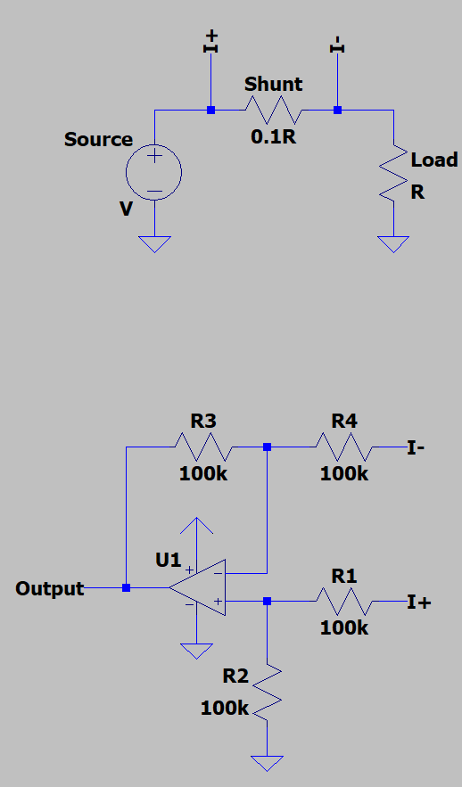
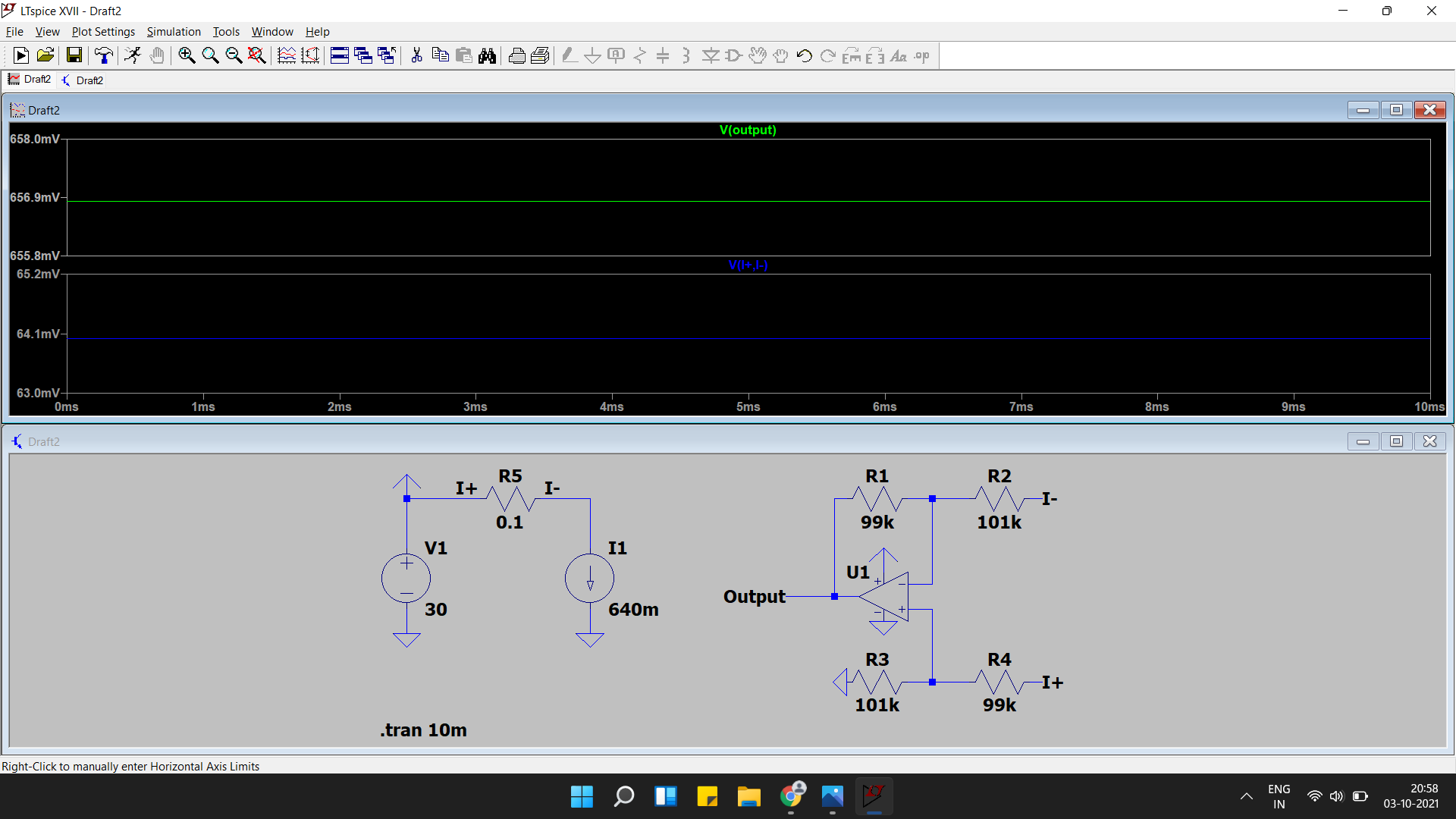
I'm currently designing a power supply and I want the power supply to have current limiting, so I designed a simple subtractor circuit to sense the output current:
To test the circuit on a breadboard, I used an LM358P op-amp, because it's a single supply op-amp and the datasheet says that its output can go all the way to zero, and I used 1% 100k resistors.
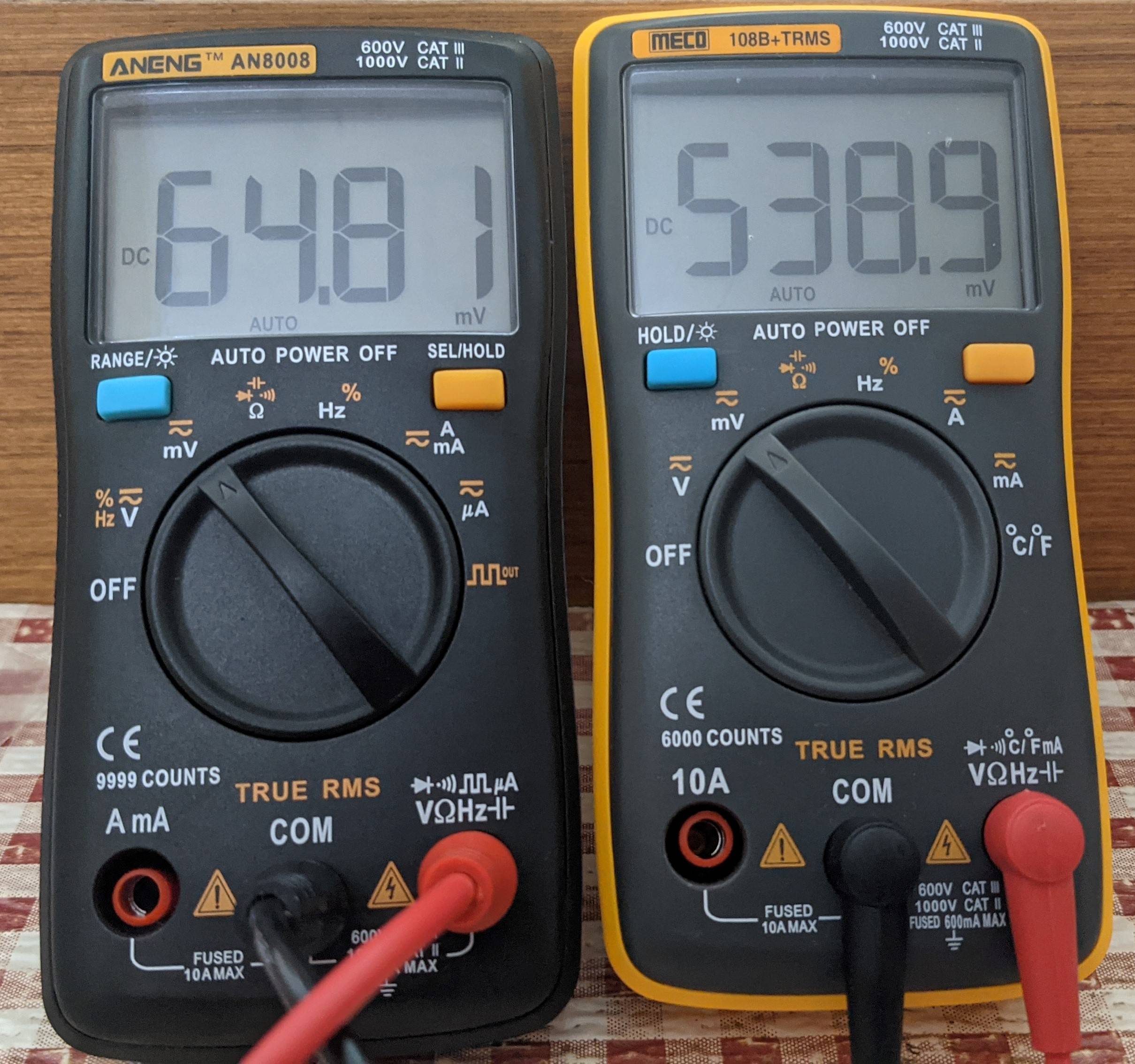
I set my power supply to 10V, connected a load and measured the voltage drop across the 0.1 ohm shunt and the output of the subtractor, and the result baffled me:
The DMM on the left reads the drop across the shunt resistor and the DMM on the right reads the output of the subtractor. It's almost 10 times higher than the expected output!
I added a 100ohm resistor to load the op-amp (I thought that the op-amp's output needs to be loaded to get a proper result), but the voltage just dropped to something like 200mV.
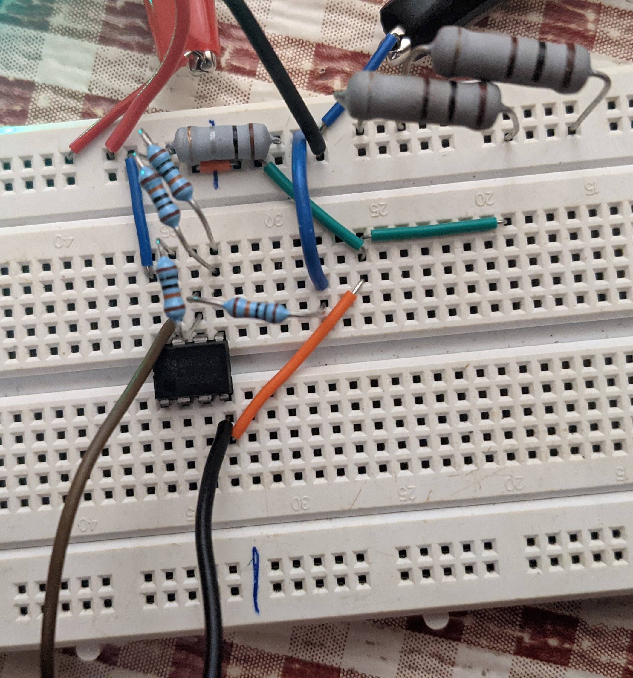
Here's a picture of my test setup:
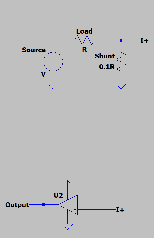
Just to make sure the op-amp is properly working, I swapped the load and the current sense resistor (low-side current sensing) and configured my op-amp as a voltage follower.
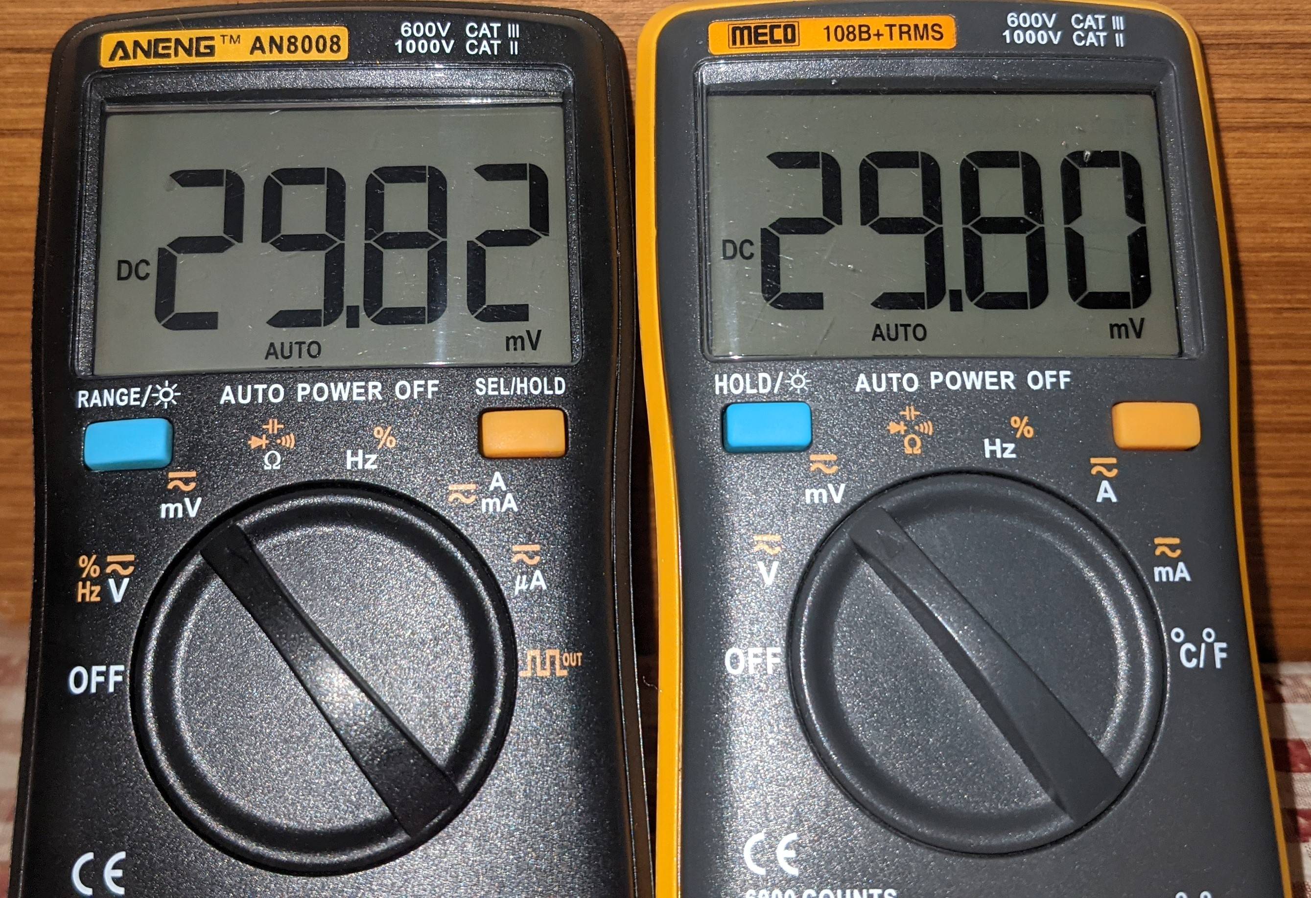
I turned on the power supply and measured the voltage drop across the shunt and the output of the op-amp, and sure enough, it works:
If the op-amp is fine (or is it?), then why does the subtractor circuit not work correctly?
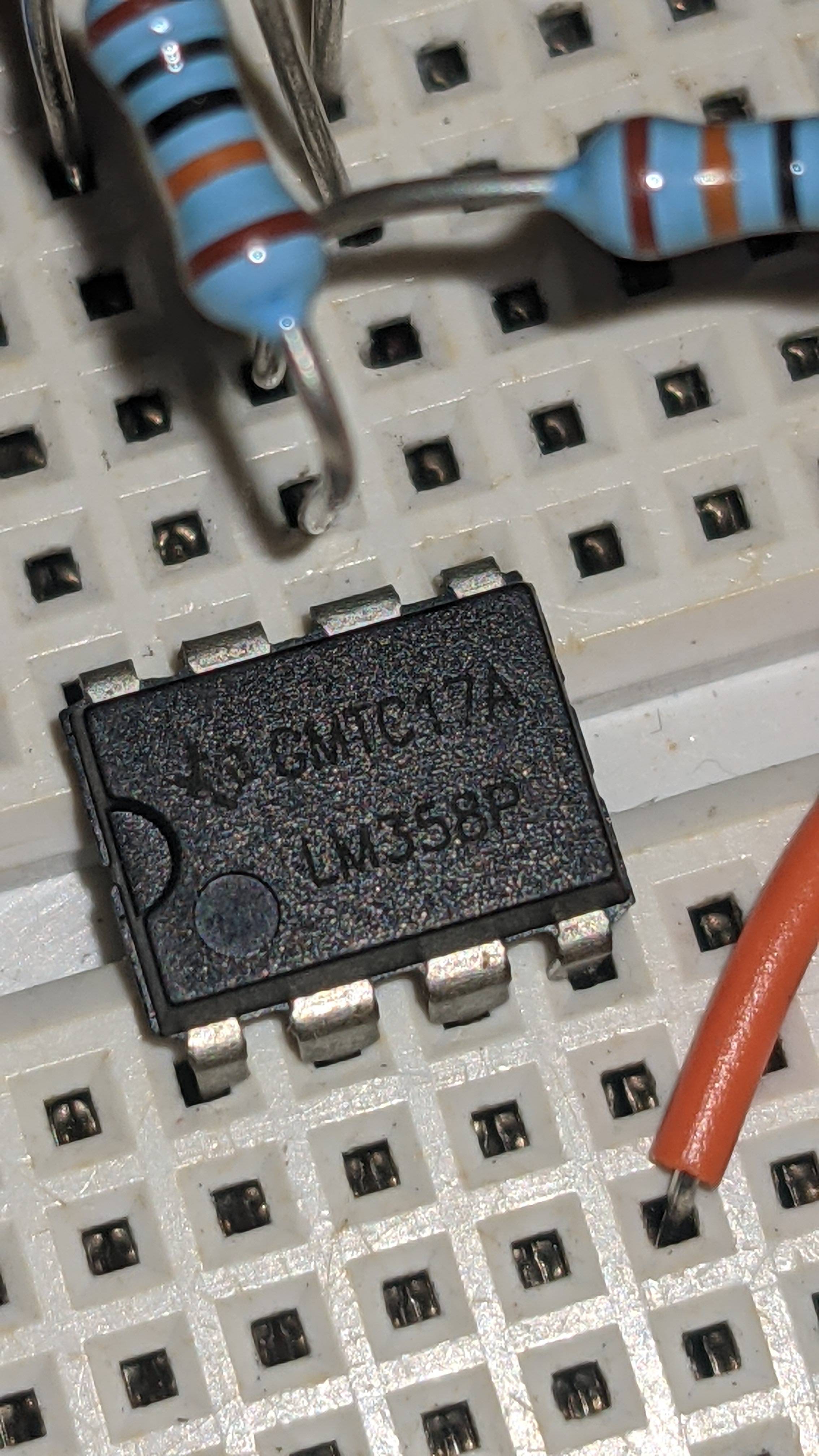
Here's a picture of the op-amp. This is a genuine part, right?
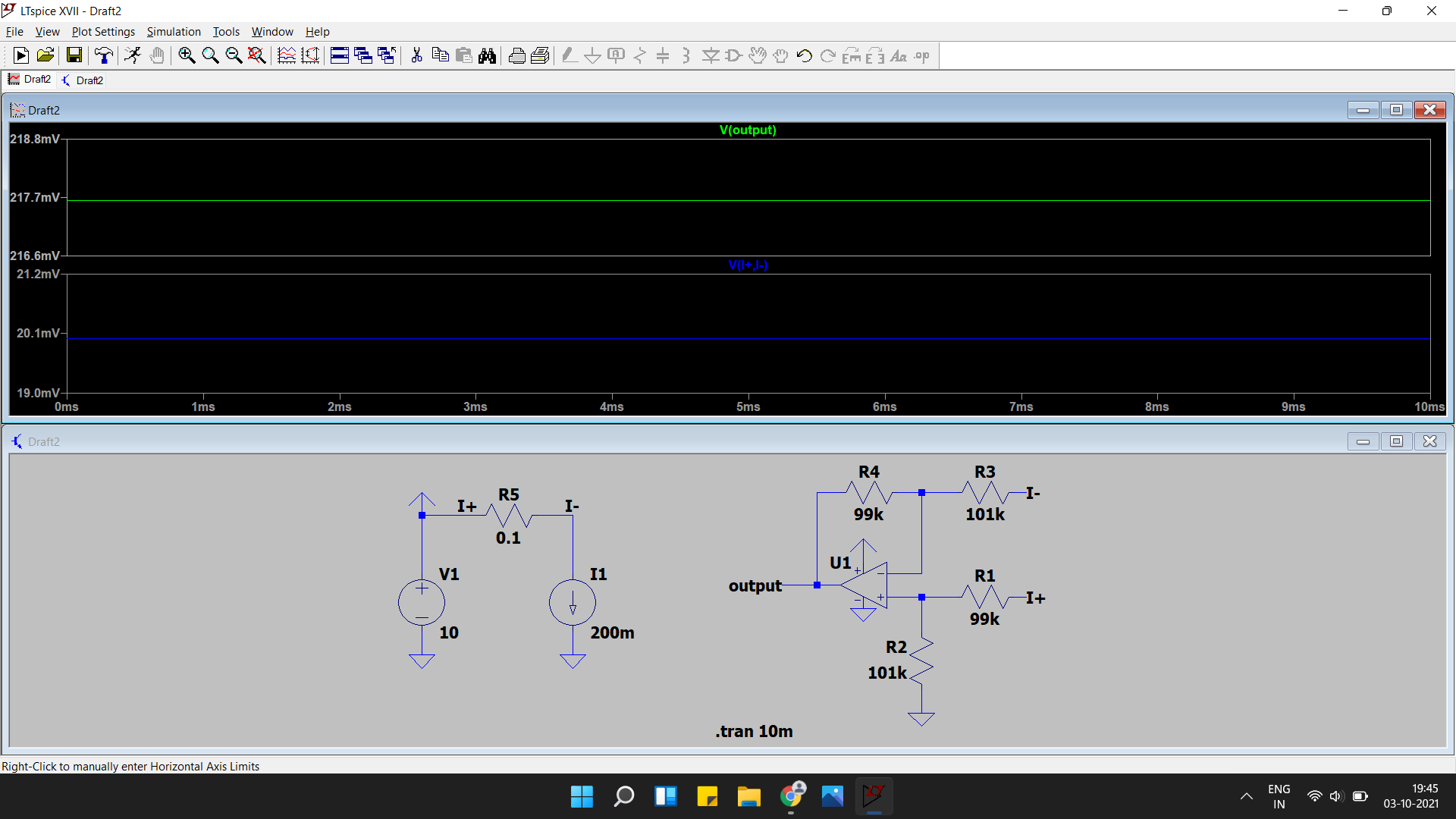
As andy suggested, 1% resistors just aren't good enough:
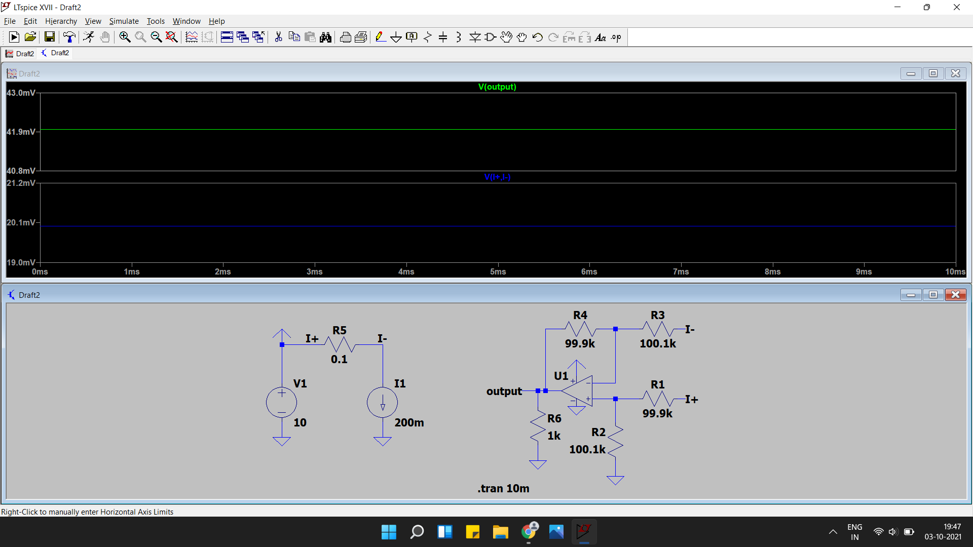
And 0.1% resistors don't give a particularly good result as well
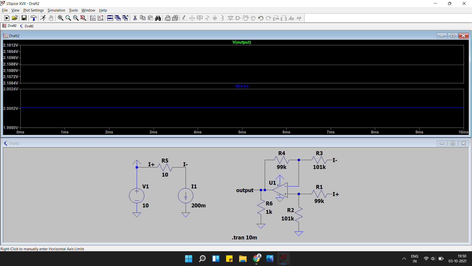
With a 10ohm shunt (Simon's suggestion) and 1% resistors, there is still a large error.
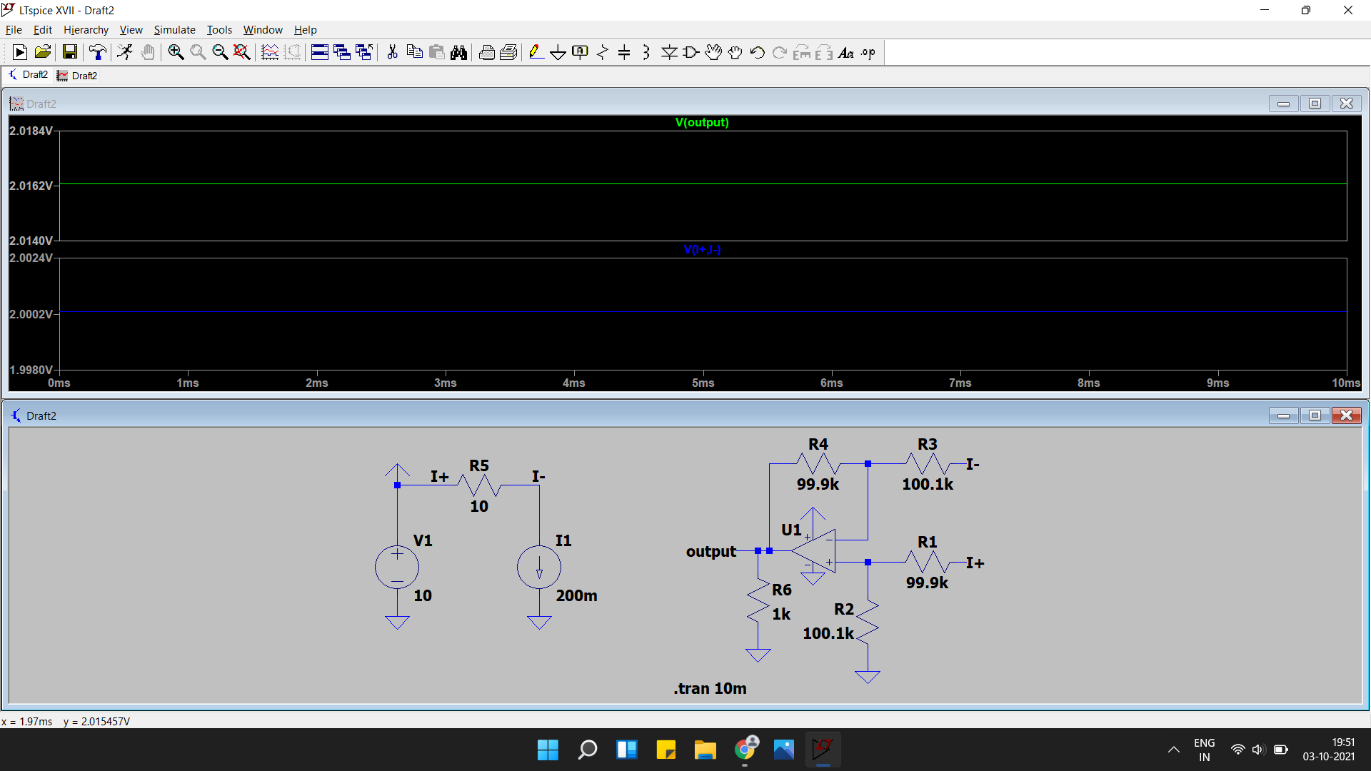
But Using 0.1% resistors here gives good results
But I obviously cant use a 10ohm shunt, so I guess I have to look for other current sensing options (like a hall effect sensor).
One last simulation for simon
Also,
reference designators as per this.
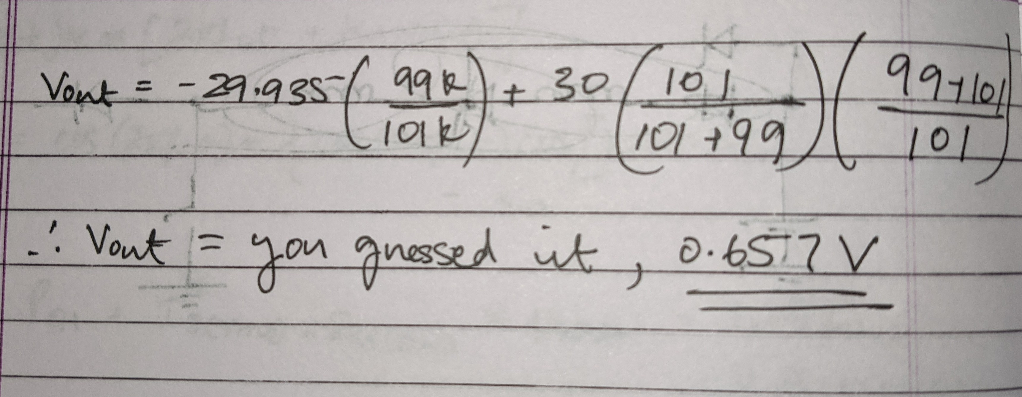
If you plug in the values,

