5
\$\begingroup\$

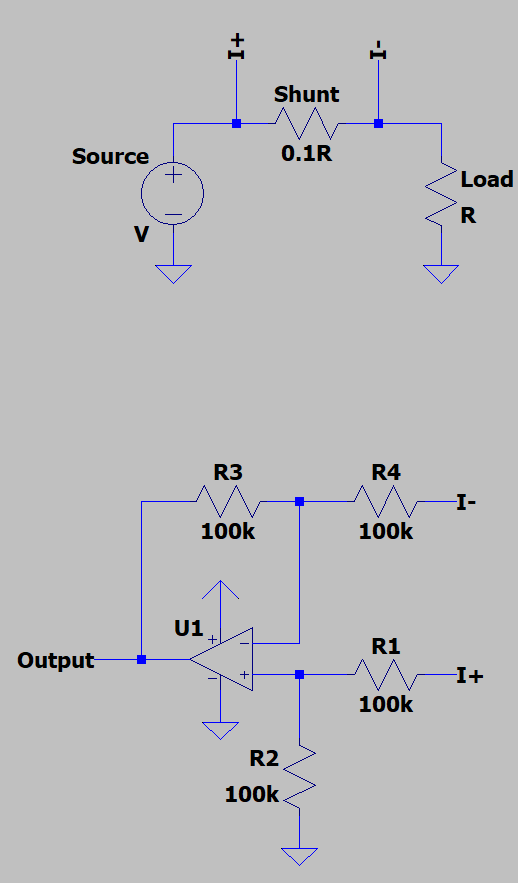
I'm currently designing a power supply and I want the power supply to have current limiting, so I designed a simple subtractor circuit to sense the output current:

enter image description here

To test the circuit on a breadboard, I used an LM358P op-amp, because it's a single supply op-amp and the datasheet says that its output can go all the way to zero, and I used 1% 100k resistors.

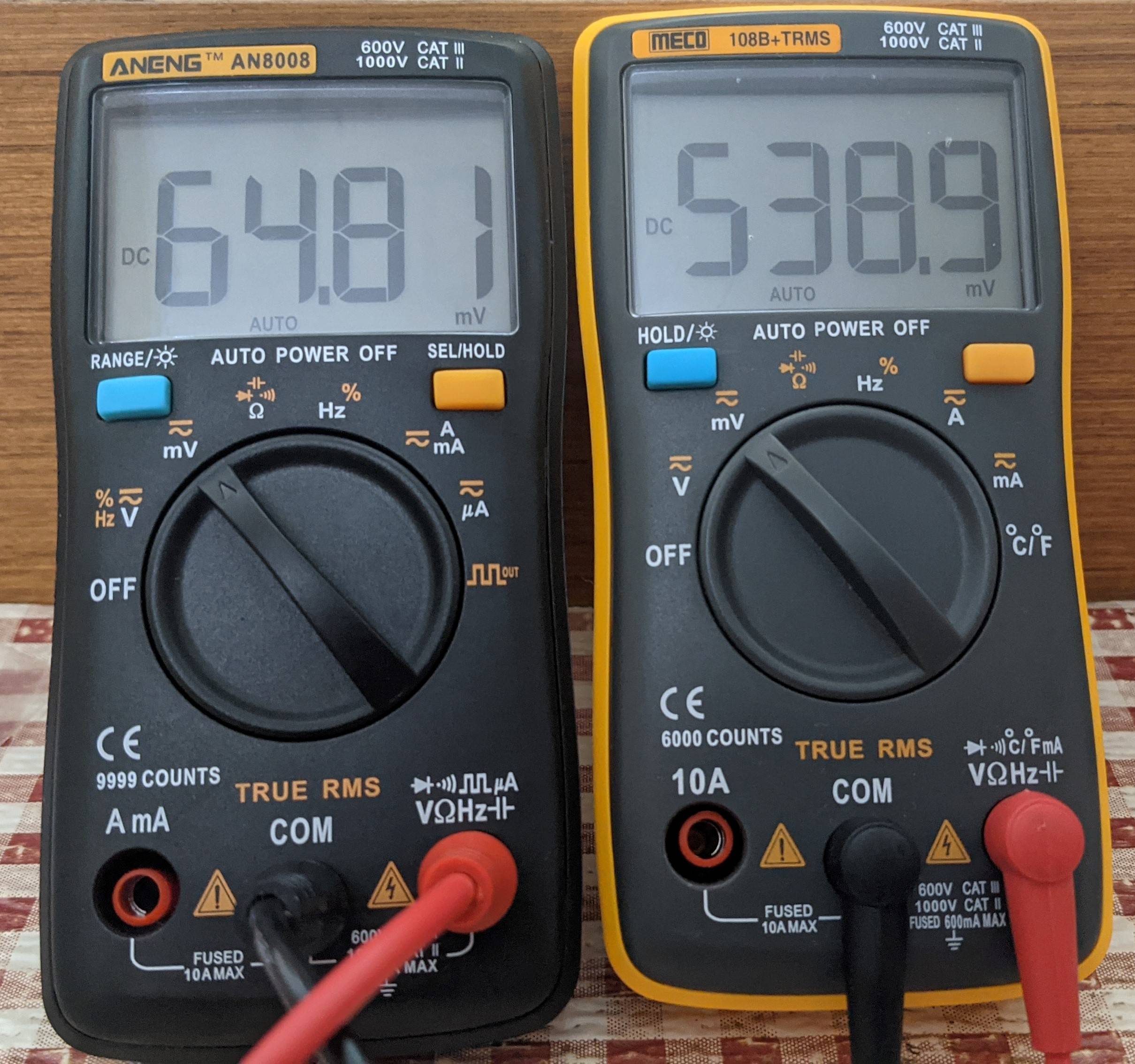
I set my power supply to 10V, connected a load and measured the voltage drop across the 0.1 ohm shunt and the output of the subtractor, and the result baffled me:

enter image description here

The DMM on the left reads the drop across the shunt resistor and the DMM on the right reads the output of the subtractor. It's almost 10 times higher than the expected output!

I added a 100ohm resistor to load the op-amp (I thought that the op-amp's output needs to be loaded to get a proper result), but the voltage just dropped to something like 200mV.

Here's a picture of my test setup: enter image description here
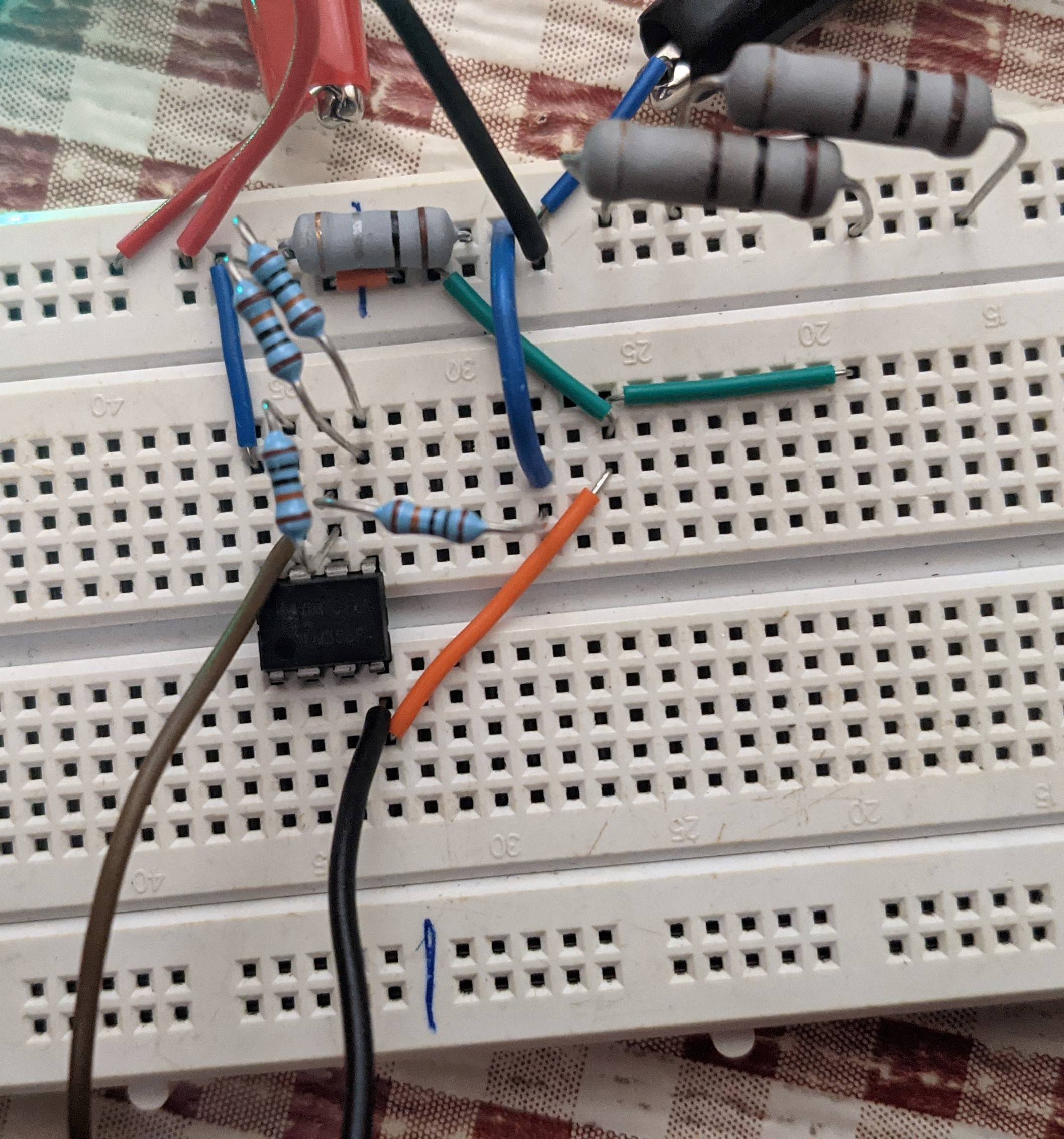
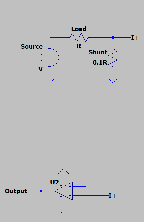
Just to make sure the op-amp is properly working, I swapped the load and the current sense resistor (low-side current sensing) and configured my op-amp as a voltage follower.

enter image description here

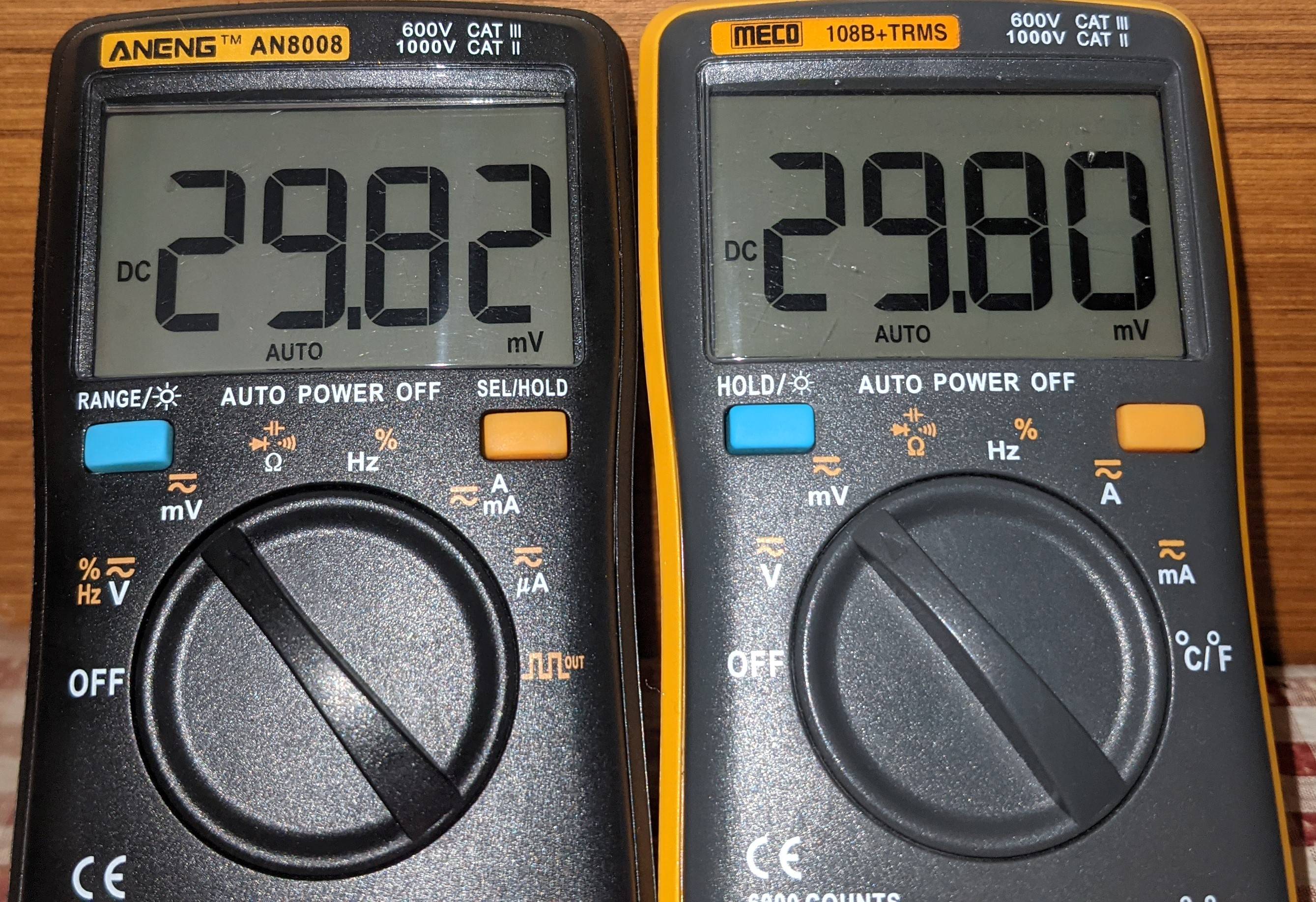
I turned on the power supply and measured the voltage drop across the shunt and the output of the op-amp, and sure enough, it works:

enter image description here

If the op-amp is fine (or is it?), then why does the subtractor circuit not work correctly?

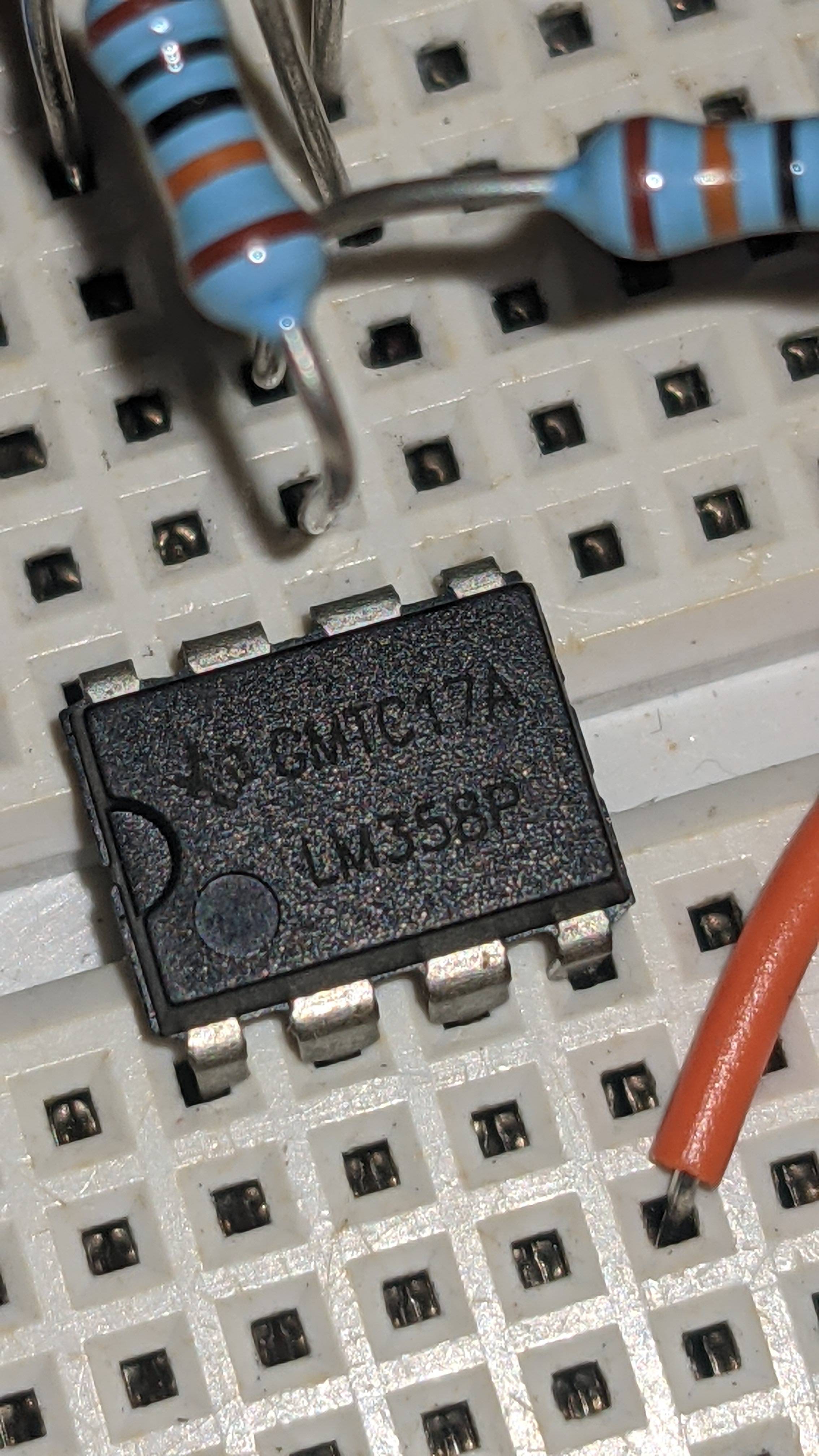
Here's a picture of the op-amp. This is a genuine part, right? enter image description here

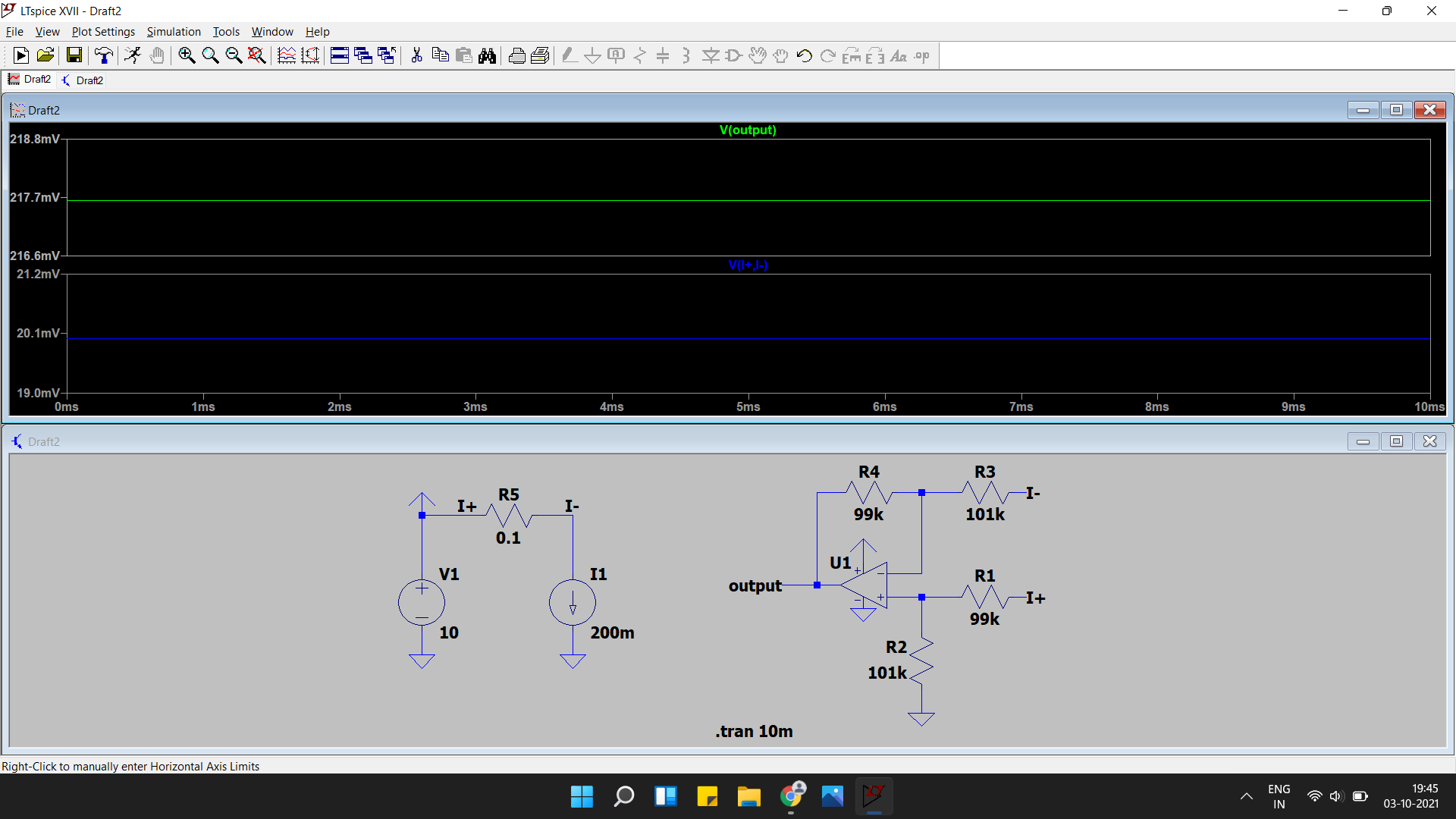
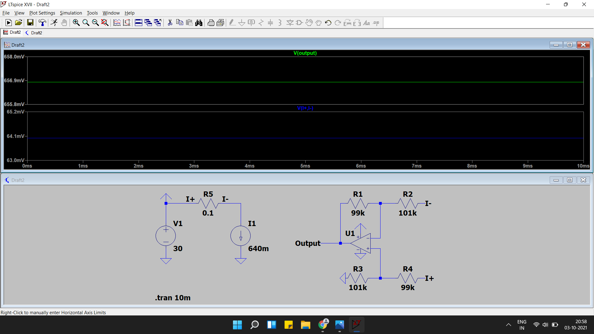
As andy suggested, 1% resistors just aren't good enough:

enter image description here

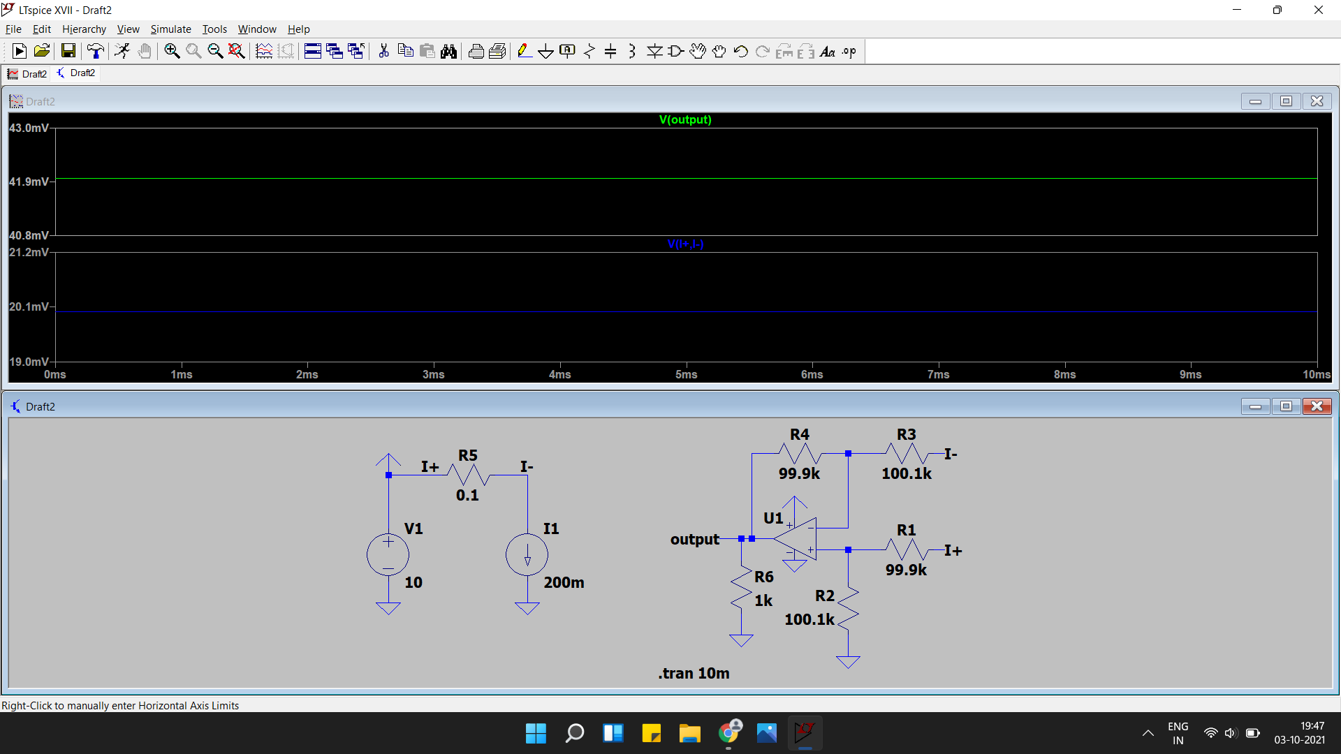
And 0.1% resistors don't give a particularly good result as well

enter image description here

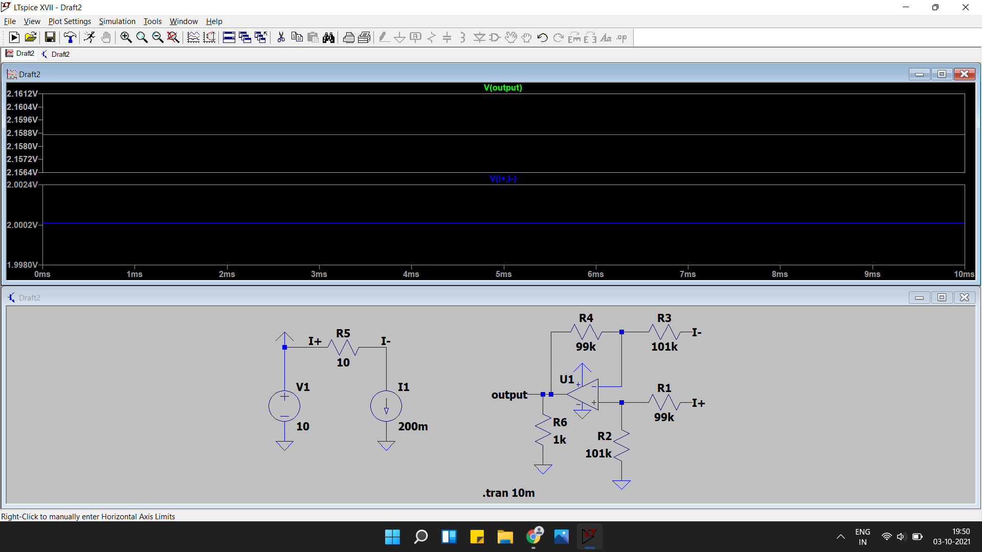
With a 10ohm shunt (Simon's suggestion) and 1% resistors, there is still a large error.

enter image description here

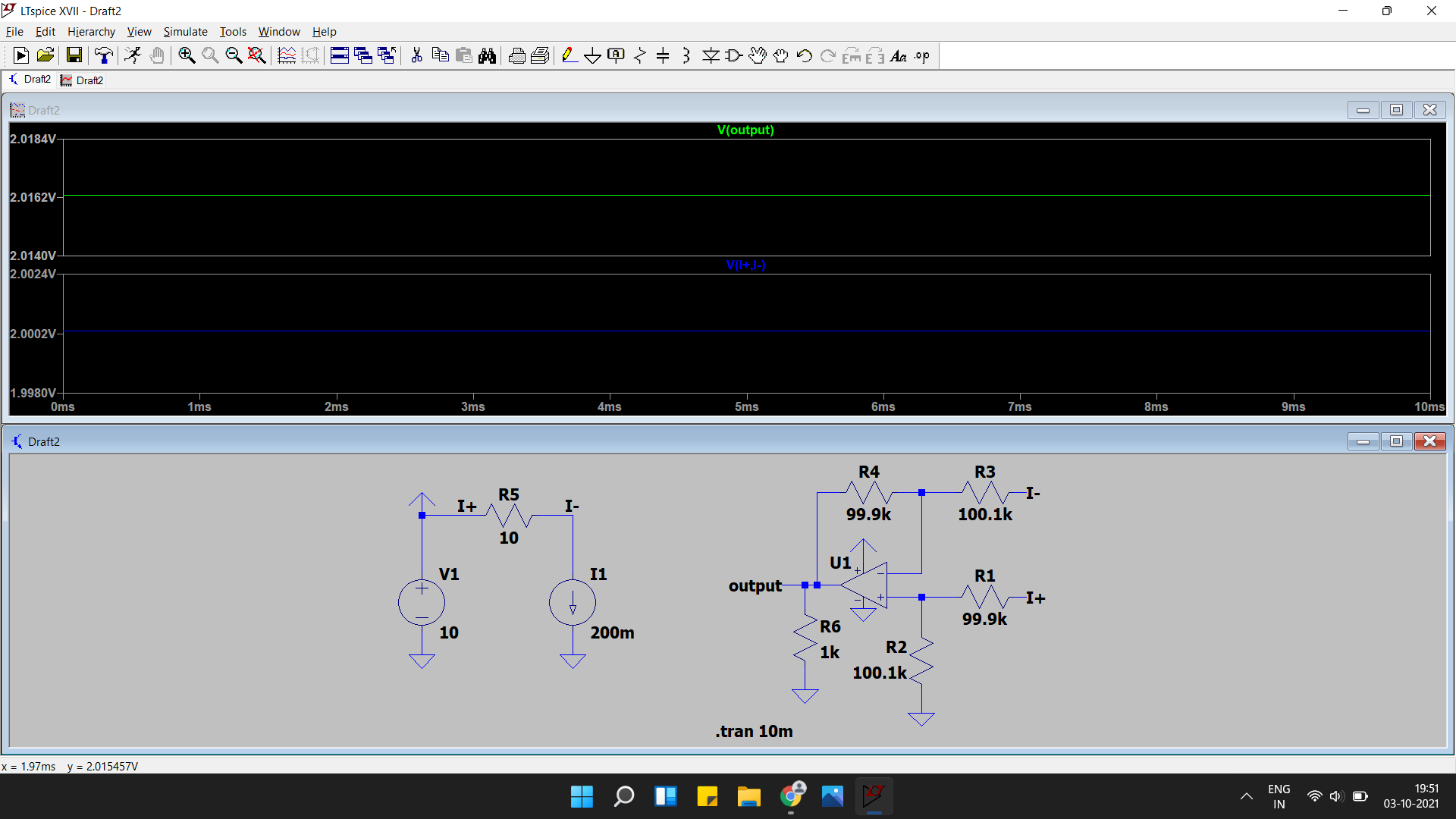
But Using 0.1% resistors here gives good results

enter image description here

But I obviously cant use a 10ohm shunt, so I guess I have to look for other current sensing options (like a hall effect sensor).


One last simulation for simon

enter image description here

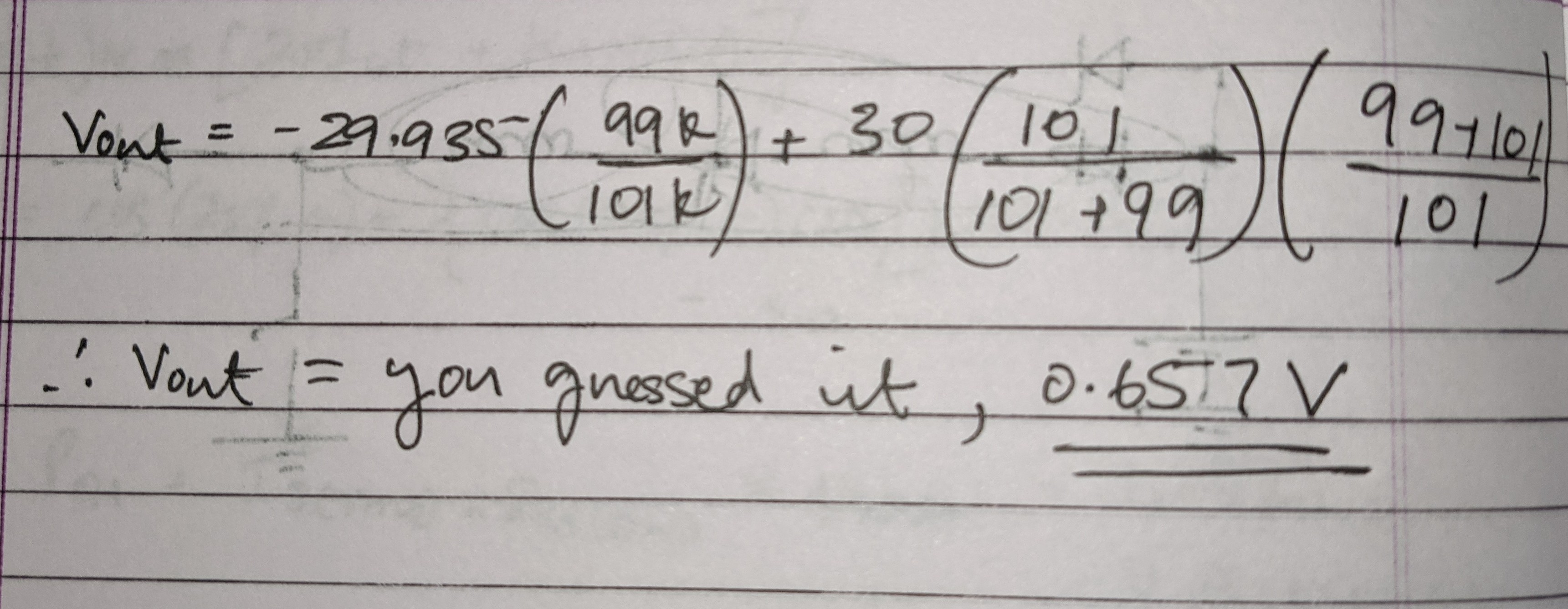
Also,

enter image description here

reference designators as per this.

If you plug in the values,

enter image description here

\$\endgroup\$
18
  • \$\begingroup\$ it should work, but maybe your 100k resistors are slightly mismatched so the gain is slightly more than -1 ? In that case the output would need to go negative. The amp will saturate and give wrong results. \$\endgroup\$
    – tobalt
    Commented Oct 3, 2021 at 12:35
  • \$\begingroup\$ Check the input common mote voltage range in the (should have been linked) datasheet. Also clarify how the opamp is powered. \$\endgroup\$
    – user16324
    Commented Oct 3, 2021 at 12:35
  • 2
    \$\begingroup\$ @user_1818839 The input common mode voltage in this circuit is pretty much mid-supply. \$\endgroup\$
    – tobalt
    Commented Oct 3, 2021 at 12:36
  • \$\begingroup\$ The LM358 is good down to the negative rail for inputs and output. \$\endgroup\$
    – Andy aka
    Commented Oct 3, 2021 at 12:52
  • \$\begingroup\$ There's nothing wrong with your schematic, or the idea, it should work. My money is on a wiring error. That photo of your circuit is next to useless, I can't see what's going where. I suggest your rebuild the circuit, in a manner that makes it easy to follow on the schematic, and doesn't hide anything in a photo. Label those wires too, they could be connected to the moon for all I know. \$\endgroup\$ Commented Oct 3, 2021 at 12:56

1 Answer 1

2
\$\begingroup\$

I set my power supply to 10V

It's completely down to the accuracy of the 100 kohm resistors. If one pair is producing a Thevenin voltage (5 volts) that is 1 % high and the other pair is 1 % low then that is +50 mV offset on one pair and a -50 mV offset on the other pair. Given that you are trying to measure a voltage of about 30 mV (if we look at your final circuit readings) you are not going to get this to work with 1% resistors. This is an age old problem with this type of circuit.

Small additional errors come from input bias offset currents running in the resistors. It can be as high as 30 nA and, 30 nA through 100 k&ohm, is an error of 3 mV. Input offset voltages are also present up to a level of about 3 mV.

\$\endgroup\$
4
  • \$\begingroup\$ So will using something like 0.1% resistors fix the problem, or should I look for other options (like a hall effect sensor)? \$\endgroup\$ Commented Oct 3, 2021 at 13:58
  • 1
    \$\begingroup\$ @PrathikPrashanth there are dedicated chips that will do this based around an op-amp whose input range includes the positive supply rail. They output a current that is a small ratio value of the measured current and, a ground connected resistor converts that current into a ground referenced positive voltage. Available from TI and ADI. Off the top of my head I can't think of part numbers but, you can build it from an op-amp and a MOSFET. OK, LT6105 springs to mind. And, I think the MAX4172 also works. \$\endgroup\$
    – Andy aka
    Commented Oct 3, 2021 at 14:49
  • \$\begingroup\$ Just for fun Andy : no one mentioned the other half op-amp floating inputs. \$\endgroup\$
    – Marla
    Commented Oct 3, 2021 at 17:01
  • \$\begingroup\$ @Marla those old dual op-amps can probably stand that situation!! \$\endgroup\$
    – Andy aka
    Commented Oct 3, 2021 at 17:32

Your Answer

By clicking “Post Your Answer”, you agree to our terms of service and acknowledge you have read our privacy policy.

Not the answer you're looking for? Browse other questions tagged or ask your own question.