0
\$\begingroup\$

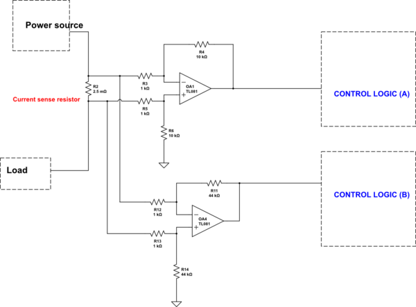
I have a current sense resistor of 0.0025 ohms where I want to connect to two differential amplifiers in parallel. I want to know if it is okay to use multiple differential amplifiers connected to the same source.

schematic

simulate this circuit – Schematic created using CircuitLab

\$\endgroup\$
2
  • \$\begingroup\$ Yes you can parallel sense amplifiers, but you are better using low side sensing to avoid significant common mode voltage. \$\endgroup\$ Commented Oct 4, 2021 at 15:02
  • \$\begingroup\$ 2.5mΩ is tiny. You'll need a current of 2A through that just to get a signal comparable with the input offset voltage of the opamp! What kind of currents are you expecting? \$\endgroup\$ Commented Oct 4, 2021 at 15:17

3 Answers 3

2
\$\begingroup\$

Yes this is completely fine as long as the signal source impedance is low. Doubling the amps also doubles the loading of the source (at a very low level).

The same is done in almost every rail-to-rail-input op-amp. They have an N-type differential pair in parallel with a P-type differential pair.

\$\endgroup\$
2
\$\begingroup\$

I want to know if it is okay to use multiple differential amplifiers connected to the same source

Generally yes; the impedance of the shunt you are using is such that any reasonable impedance in parallel is not going to significantly reduce the shunt resistance by very much at all.

However, the circuit you are using may be wholly faulty whether you have one or two in parallel. This is mainly because the common mode voltage on the current sense line might be a lot higher than the voltage dropped across the shunt and, any very slight tolerance induced resistive imbalance on the differential amplifier inputs will make a mockery of any small millivolt signal you are trying to measure.

Short story: Your measurement circuit is possibly flawed (especially if using a TL081 with a several millivolt input offset voltage).

See this recent Q and A for a deeper explanation.

If the op-amp resistors are perfect: -
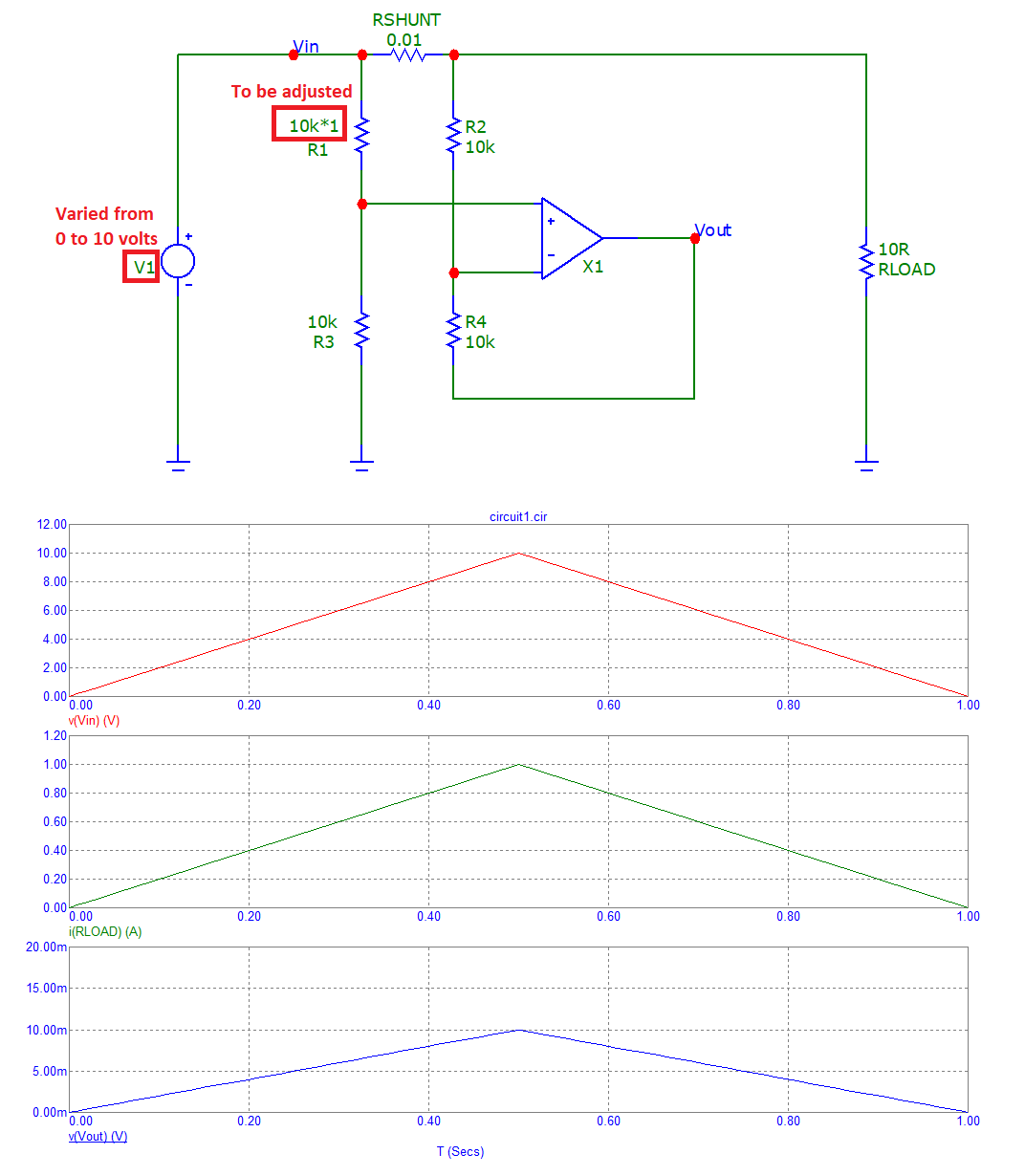
enter image description here

The output from the op-amp rises from 0 volts to +10 mV as expected. If we lower R1 by 0.1%: -
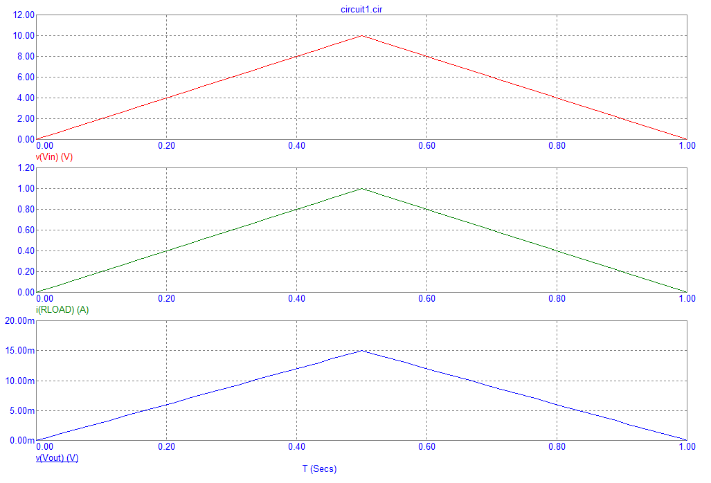
enter image description here

Now, there is a 50% error in the output signal; instead of producing 10 mV when the input supply is 10 volts, 15 mV are produced.
\$\endgroup\$
1
  • 1
    \$\begingroup\$ @SudipKongbrailatpam read this carefully. Making a faulty op-amp circuit due to insufficient common-mode voltage range is a rather common mistake (the most common one ?). \$\endgroup\$
    – tobalt
    Commented Oct 4, 2021 at 14:42
1
\$\begingroup\$

Yes, you can do that.

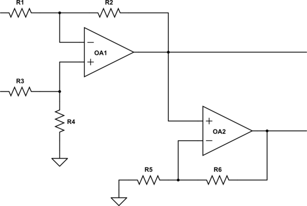
It will probably be cheaper and take less board space to have the DA drive one block, while putting a non-inverting amp on the output and using that to drive the other block, adjusting gain as desired.

schematic

simulate this circuit – Schematic created using CircuitLab

\$\endgroup\$

Your Answer

By clicking “Post Your Answer”, you agree to our terms of service and acknowledge you have read our privacy policy.

Not the answer you're looking for? Browse other questions tagged or ask your own question.