0
\$\begingroup\$

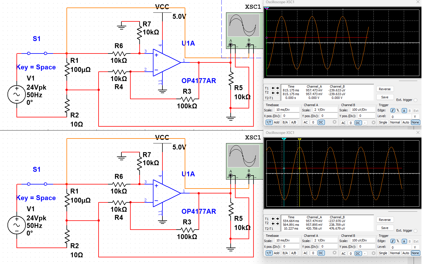
I'm trying to simulate a current sensing op-amp circuit. My AC voltage, 24 VAC, is across a load of 10 Ω. I used a 100 μΩ resistor and measured the voltage across it using an op-amp.

Looking at some reference designs, what I have done for a high-side current sensing circuit seems to be correct, and I made sure to select an op-amp that has a low offset voltage (60 μV), but as you can see there is no voltage change across the op-amp output.

Could someone please explain what I am doing wrong here?

enter image description here

\$\endgroup\$
3
  • \$\begingroup\$ at minimum I would start with a higher shunt resistance until you get things working - 100uV is very low considering it's going to drop only 240uVRMS. Your offset error is going to be over 20% alone even if your circuit works perfectly. \$\endgroup\$
    – MOSFET
    Commented Jan 30 at 22:49
  • \$\begingroup\$ Try a bigger sense resistor (20mOhm or so) and less gain. Also, is your AC referenced to ground somehow? \$\endgroup\$ Commented Jan 31 at 0:32
  • \$\begingroup\$ In addition to comments above 1) what simulation tool are you using? It may simulate correctly that the grounds of channels A and B are connected together, thus grounding the lower side of R1. 2) The resistor ratios for the inverting and non-inverting side of a difference amp need to be balanced, or you will have terrible common mode rejection ratio. \$\endgroup\$ Commented Jan 31 at 1:55

2 Answers 2

0
\$\begingroup\$

The VCC is only 5V, this means the CMRR is +/-3.5V. at times you have 12V on the positive rail. Either move the VCC up past 12V or move to a low side configuration. Low side is much easier to maintain CMRR

\$\endgroup\$
0
\$\begingroup\$

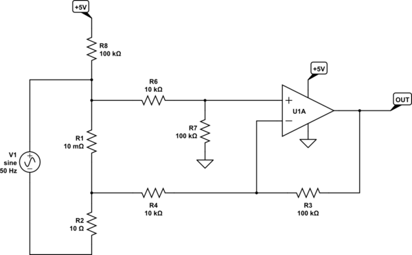
I've made a few changes, which I'll explain below:

schematic

simulate this circuit – Schematic created using CircuitLab

  1. R7 should be the same as R3, otherwise you have a large common-mode gain, and the op-amp will saturate even if the input signals are equal.

  2. I've increased R1, the current sense resistance. With V1 at 24V, and R1 at 100μΩ the voltage across this resistor will be:
    $$ V_{R1} = I_{R1}R_1 \approx \frac{V_1}{R_2}R_1 = \frac{24V}{10\Omega}\times 100\mu\Omega = 240\mu V $$
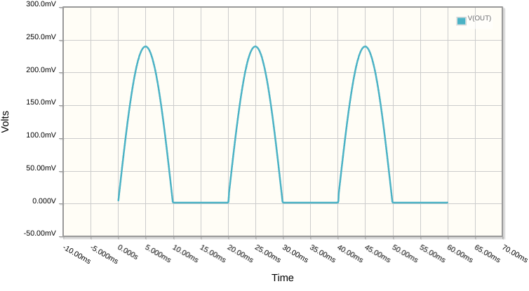
    That's way too small. With a subsequent gain of 10, that becomes 2.4mV, and that's still below the lowest possible output voltage from your op-amp. I've increased R1 to 10mΩ, a factor of 100, so we should expect 240mV peak output.

  3. Perhaps most importantly, I've added R8, to raise the common mode voltage of the two inputs well above ground. Without R8, the inputs are essentially floating, and both op-amp inputs were too close to 0V, outside their acceptable range of input potentials. Now they hover somewhere near 1.7V, which is well within the op-amp's requirements.

This is what I get at OUT:

enter image description here

\$\endgroup\$

Your Answer

By clicking “Post Your Answer”, you agree to our terms of service and acknowledge you have read our privacy policy.

Not the answer you're looking for? Browse other questions tagged or ask your own question.