9
\$\begingroup\$

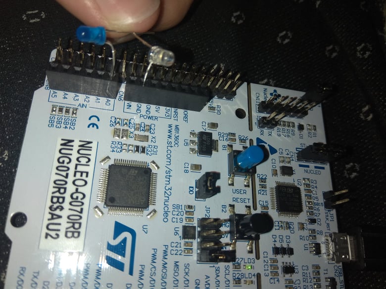
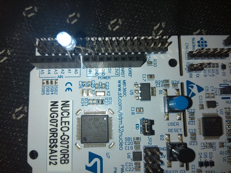
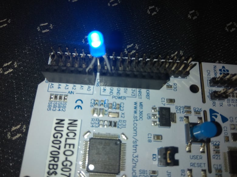
I'm very new to electrical engineering and I ran into a strange issue while trying to connect two LEDs in series today. Both my blue and white LEDs work separately, but when I try to connect them together, they do not work (see pictures). Is there something I'm doing wrong?

(I did try changing the orientation of the LEDs to make sure my cathodes and anodes are connected to where they're supposed to be)

Two LEDs in series not working

White LED working

Blue LED working

\$\endgroup\$
1
  • 4
    \$\begingroup\$ Since you're new to electrical engineering, it is in fact generally the case that most electronic devices will not "work" simply by connecting them to whatever you feel like, or to whatever you have within arms reach. All electronic components come with datasheets which give you the critical information required to make them do what they are designed for and it is your role as the circuit designer to ensure that you provide the components with the appropriate inputs to that end. Guess and check is a doomed strategy - you must learn to calculate, plan, and design. \$\endgroup\$
    – J...
    Commented Nov 16, 2021 at 14:57

2 Answers 2

40
\$\begingroup\$

The LEDs both need about 3V to work, so together in series they need about 6V to work, but the IO pin only gives out 3.3V. So there is no way the LEDs could work in series.

Also do not connect LEDs to IO pins without series resistors to limit the current, current might be too high and the MCU or LED could be damaged permanently.

\$\endgroup\$
3
  • 8
    \$\begingroup\$ 2:15 am . sitting in a hospital room keeping someone company. Decided to answer the question You were 2 minutes quicker :-). \$\endgroup\$
    – Russell McMahon
    Commented Nov 15, 2021 at 13:25
  • 1
    \$\begingroup\$ I know it's common to refer to resistors in this configuration as current limiting, but I think the term oversimplifies the actual mechanics. Since I = E / R, as you change the voltage the current also changes and the resistor does nothing to compensate. \$\endgroup\$ Commented Nov 16, 2021 at 4:09
  • 5
    \$\begingroup\$ Simplifies it, certainly. But the resistor is "current limiting" in the sense that the current through it is only about linear in voltage, whereas without it, the current through the LED would be roughly exponential in voltage, which in practice means it would be huge and easily destroy the LED for most voltage ranges where anything happens at all. So with the resistor it's much more limited. \$\endgroup\$ Commented Nov 16, 2021 at 6:59
20
\$\begingroup\$

LEDs have a forward operating voltage "Vf".This varies with current but is around 3V for both blue and white LEDs at typical operating currents. If you place 2 LEDs in series they would require about 6 volts to provide a Vf of 3 V for each.

In this case you are fortunate that the supply voltage has been current limited enough not to destroy the LEDs. Applying voltage sources well above normal operating Vf will allow large currents to flow and will usually destroy the LED.

Proper practice is to provide a series resistor to drop the extra voltage and to limit current.
Voltage drop is Vsupply - Vf = Vr. Resistor value= V/I = Vr / I_wanted.

Here if Vsupply = 5V, I = 10 mA, Vf = 3V. R = (5-3)/0.010 = 200 Ohms (approximately).

Source current limitations will reduce actual current when supply is from eg processor pins.

\$\endgroup\$
2
  • 3
    \$\begingroup\$ I see from your comment on another answer that you were in a hospital room when you wrote this answer. On your phone I assume. I only mention it because auto-correct converted "voltage" to "village". \$\endgroup\$ Commented Nov 16, 2021 at 3:55
  • 1
    \$\begingroup\$ @MarkRansom THanks. Devillageafied, and a few other typos. \$\endgroup\$
    – Russell McMahon
    Commented Nov 16, 2021 at 7:03

Your Answer

By clicking “Post Your Answer”, you agree to our terms of service and acknowledge you have read our privacy policy.

Not the answer you're looking for? Browse other questions tagged or ask your own question.