0
\$\begingroup\$

enter image description here

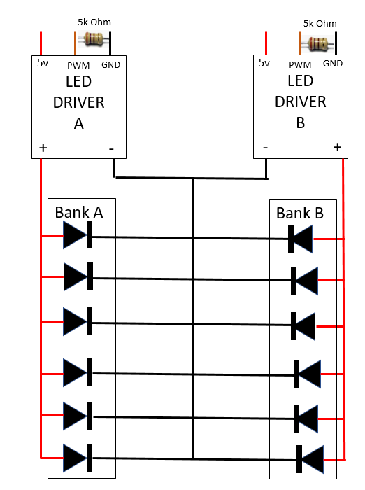
I am having an issue with the above circuit when LED DRIVER B has 0 PWM and LED driver A is being driven by a signal driver B is supposed to be off but the leds from BANK B are still lit dim. I checked with a scope and have 0 PWM on LED DRIVER B. One LED from BANK A is enclosed with one LED from BANK B. Bank A is white LEDs and BANK B is Green LEDs. The same issue happens in reverse. When LED driver B has a PWM and LED driver A does not, all LEDs are on. I was not involved with the design and need to find a way to fix this. The LED's are very difficult to get to and it is a last resort to modify the boards they are on by separating the grounds. The banks are never supposed to be on at the same time. When one turns off the other turns on and both are supposed to dim up or down at the same time. The drivers for this circuit are LDD-1500L https://www.meanwell.com/Upload/PDF/LDD-L/LDD-L-SPEC.PDF. I am hoping someone can provide a solution to this without modifying the boards they are on.

We did try adding a diode at the - outputs of the driver to block any possible feedback into the driver but this did not work.

\$\endgroup\$
4
  • 4
    \$\begingroup\$ the PWM probably opens and closes the ground since that's easier and cheaper to do than high-side switching. use drivers that switch high-side and keep the ground constant. you simply can't use the drivers you mention in a common ground config. \$\endgroup\$
    – dandavis
    Commented Apr 29, 2019 at 19:39
  • 2
    \$\begingroup\$ Please edit your question to add a link to the datasheet for the drivers. \$\endgroup\$
    – Transistor
    Commented Apr 29, 2019 at 19:39
  • \$\begingroup\$ Why are these drivers supplied by 5V? Acc spec, input should be 6 ~ 36 VDC \$\endgroup\$
    – Huisman
    Commented Apr 29, 2019 at 20:07
  • \$\begingroup\$ Because the leds that are being used are 3 volt leds. I can only drive them up to 2.9 V because of temperature concerns. I will add the link to the data sheet in the question. \$\endgroup\$
    – pleslie
    Commented Apr 30, 2019 at 12:29

2 Answers 2

0
\$\begingroup\$

EDIT
This answer is based on the (wrong) assumption that neither the leds (PCB) nor the LED drivers, nor the connection between both should be changed/replaced.

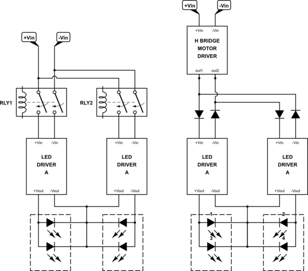
Since the input current is not that much (less than 1.5A), you could try disabling the power supply of LED driver A (interrupt 5V as well as GND) when LED driver B is controlled and vice versa.
It is an ugly solution, but it might work.
If you need to switch quickly between drivers, you can replace the relays with (high and low side) mosfets. Or replace it with a motor driver with rectification.

schematic

simulate this circuit – Schematic created using CircuitLab

\$\endgroup\$
4
  • \$\begingroup\$ Would there be any negative side effects of just putting a relay on the +Vout of each driver and turning that on and off when I want each bank to be used. \$\endgroup\$
    – pleslie
    Commented Apr 30, 2019 at 15:59
  • \$\begingroup\$ I know this goes against my requirement of needing to dim up and down at the same time but this may be an allowable compromise and I will just dim one side down open the relay and then dim the other side up. \$\endgroup\$
    – pleslie
    Commented Apr 30, 2019 at 16:12
  • \$\begingroup\$ Would there be ... used. I thought you couldn't replace neither the leds (PCB) nor the LED drivers, nor the connection between both. However, if you are able to insert relays, why not dismiss the current LED drivers and pick other LED drivers that allow for common cathode instead? \$\endgroup\$
    – Huisman
    Commented Apr 30, 2019 at 20:41
  • \$\begingroup\$ @pleslie You can use the relays on the outputs of the drivers. If each bank is completely dimmed, the relays are switched at zero current. That is the best way of switching a relay. \$\endgroup\$
    – Huisman
    Commented May 1, 2019 at 4:42
1
\$\begingroup\$

enter image description here

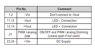
Figure 1. The pinout for pins 1 and 2 suggests that there are some internal constraints and that there is switching between -Vout and -Vin.

... it is a last resort to modify the boards they are on by separating the grounds.

If the LEDs are common cathode then switching the grounds won't work.

The banks are never supposed to be on at the same time. When one turns off the other turns on and both are supposed to dim up or down at the same time.

There's a conflict in what you are describing here. If they both dim up and down at the same time then there must, at least, be some overlap when they are both on.

schematic

simulate this circuit – Schematic created using CircuitLab

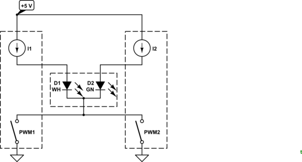
Figure 2. Equivalent circuit. The PWM switches are most likely to be in the LED negative leg.

I think you can't fix this with those power supplies.

\$\endgroup\$
1
  • \$\begingroup\$ You are correct my statement is conflicting about not being on at the same time. What should have been said is the they dim up or dim down at the same time.If A dims up then B dims down. If B dims up then A dims down. Only after the dimming will one be on and one be off. There is no time in which both banks are getting full pwm at the same time. \$\endgroup\$
    – pleslie
    Commented Apr 30, 2019 at 12:35

Your Answer

By clicking “Post Your Answer”, you agree to our terms of service and acknowledge you have read our privacy policy.

Not the answer you're looking for? Browse other questions tagged or ask your own question.