4
\$\begingroup\$

High school electronics student here, so sorry if this is a simple question.

I have a photo-electric sensor that I currently have hooked up to a microcontroller.

When on, the digital input it always reads high. When connected to an MCU analog input, the input changes when the sensor is triggered between 200 (low) and 2000 (high). In other words, it is a digital sensor, but its output isn't exactly digital - it is more of '0.1 or 0.9' instead of 0 or 1.

Is there some type of IC that I would be able to use to convert it to a true digital signal?

\$\endgroup\$
5
  • 8
    \$\begingroup\$ Can you share the datasheets and circuit diagram? You might actually be experiencing some other problem. \$\endgroup\$
    – Ralph
    Commented Mar 7, 2022 at 21:17
  • 6
    \$\begingroup\$ "When on the analog input, the input changes when the sensor is triggered between 200 (low) and 2000 (high.)" - what voltages do these numbers represent? \$\endgroup\$ Commented Mar 7, 2022 at 21:31
  • \$\begingroup\$ Photoelectric sensors often have an open collector output, so it might be as simple as adding a pullup resistor. \$\endgroup\$
    – GodJihyo
    Commented Mar 7, 2022 at 22:40
  • 1
    \$\begingroup\$ 0.1 and 0.9 are within limits of being proper logic high and low. Unless you share info which sensor it is, how it is powered and to where it is connected to read analog or digital pin, there's no way to know what has gone wrong. There is a chance that your question how to turn it to proper digital signal is not the correct question to solve the problem. \$\endgroup\$
    – Justme
    Commented Mar 8, 2022 at 11:49
  • 1
    \$\begingroup\$ As everyone here has asked, please can you edit your question and add: circuit diagram (not a link to it), and a link to the datasheet of the sensor. Thanks. \$\endgroup\$
    – TonyM
    Commented Mar 9, 2022 at 9:03

5 Answers 5

12
\$\begingroup\$

Is there some type of IC that I would be able to use to convert it to a true digital signal?

Yes, you can use a voltage comparator IC.

The comparator will compare the voltages on its two input. When one is greater than the other, its output will go high otherwise it will go low.

'High' and 'low' can be chosen to be logic voltages so you can drive your MCU input pin directly. Some have open-collector/open-drain outputs and need a pull-up resistor.

You would connect your sensor's output to one comparator input pin and a reference voltage Vref to the other input pin. Vref sets the threshold voltage. When your sensor crosses that threshold voltage, the comparator output goes from low to high, or high to low depending on how you've connected it.

Vref can be driven from an preset potentiometer, so you can experiment.

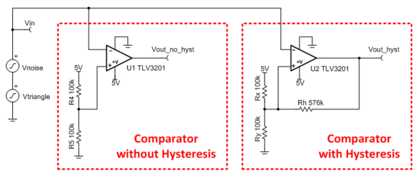
Below is an example comparator circuit, taken from this Texas Instruments design document which explains all the theory behind comparators and how to design a circuit in practice.

It explains that you can connect up your comparator with hysteresis or without. Hysteresis stops the comparator output 'chattering' (flipping between high and low fast) when the inputs are nearly equal voltage. It's worth using here as it only needs one extra resistor and makes the output far more stable.

enter image description here

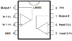
An example part is the LM393 (shown below) which contains two comparators in a friendly 8-pin DIL package.

Note that you can buy MCUs with a comparator built in. Often, the comparator input pins go to the MCU input pins or one comparator input can be driven by an internal DAC to provide Vref, which can then be programmed through software.

enter image description here

\$\endgroup\$
8
\$\begingroup\$

It's common for digital electronics to not go all the way to 0 V or supply voltage. The sensor datasheet will state what is the minimum high voltage (for example 0.9 * Vsupply) and maximum low voltage.

Similarly the microcontroller will have threshold values for input high and low. I assume the 0.1 and 0.9 are just guessing, if it doesnt register it's probably further from 0 and 1 (supply voltage) in reality, as usually 10 % and 90 % of the voltage would be accepted as 0 and 1. You could use a schmitt trigger IC or a logic buffer IC that has desired input threshold, but in case you need to set the thresholds exactly you need to use a comparator.

Or just leave it in the analog input and set the thresholds in firmware.

\$\endgroup\$
6
\$\begingroup\$

Logic Thresholds

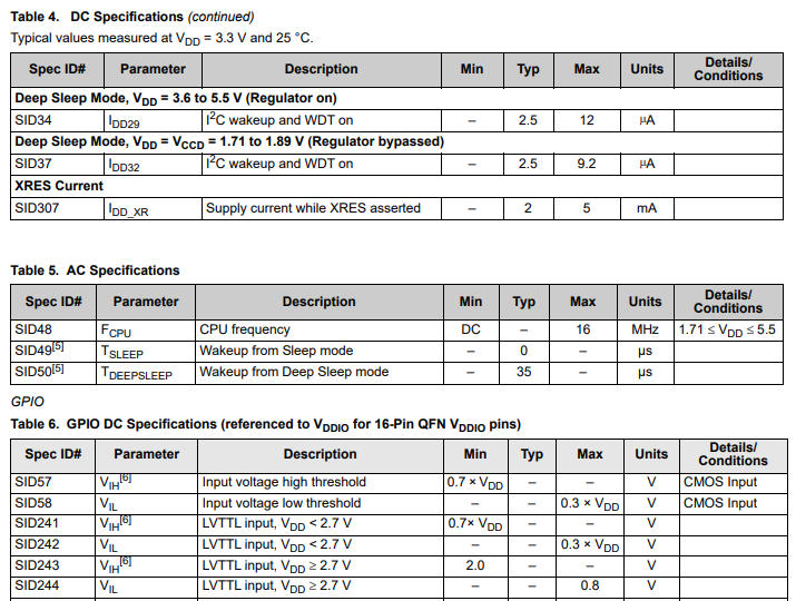
Thresholds for logic IC's are defined in datasheets are much tighter than 10% and 90% of V+. Many can use 40% to 60%, others 1V to 2V so a true digital signal only has to obey the logic datasheet requirements.

All logic IC's have analog specs to define the interface V,I range.

Datasheets recommend margins for noise rejection which tend to be around 1/3 to 2/3 of the CMOS supply voltage often called Vdd or just V+.

In micro-controller units (MCU or uC) it is common to define the logic thresholds can vary over temperature and tolerances from 30% to 70% so the input low =0 or Vil maximum must be below 0.3V+ or 30% of the supply and high minimum or Vih =0.7 must be above 70% V+.

Thus 10% to 90% easily meets this logic spec. enter image description here

There also exists inverters with hysteresis or backlash that use the above thresholds. Thermostats for homes do have hysteresis of about +/-0.5 'C so for light, it is important to decide if you need a sharp transition without noise and how much hysteresis you need might be much smaller than 1/3 to 2/3 Vdd.

Light sensors

There exists many light sensitive sensors that either change resistance (LDR) or convert light to current (PD).

CMOS Logic normally has a mid-range threshold to analog voltages with high impedance.

Therefore from Ohm's Law and knowing the uA of current threshold you desire for "0,1" you choose that value of pullup resistance to create the voltage across the sensor.

Here is a recent discussion on LDR's and Light Sensors What is the mathematical relationship between the resistance of an LDR and light intensity in lux?

Conclusion

Sometimes you need an IC to buffer an analog voltage to create a logic signal, other times all you need is just a the sensor with resistance directly into any logic IC to create the logic levels needed for switching something. The details come in the datasheets of the sensor and interface desired. 74HC... family of CMOS logic is the basic simple CMOS logic gates that are often used.

\$\endgroup\$
3
\$\begingroup\$

"Digital" is in the eye of the beholder, not a property of electricity itself.

(Warning: the following explanation is a bit hand-wavy. I'm trying to get the general idea across, rather than give an exact engineering explanation.)

The electrical voltages and currents between devices are always analogue. When we build "digital" systems we assign meanings to particular voltage¹ levels (called the "logic levels") within circuits and then design the system to signal via voltage levels in those ranges. A common one in hobbyist electronics today (and in a lot of commercial electronics through the 1990s) is 5 V TTL, where typically 0.0-0.8 V is read as "low" or "zero" and 2.4-5.0 V is read as "high" or "one." (Anything in between 0.8 V and 2.4 V is an invalid signal and may cause undefined behaviour in the system.) A similar one is 5 V CMOS logic which has tighter range requirements, typically 0.0-1.5 V for "low" and 3.5-5.0 V for "high."²

While this sounds simple, you cannot ignore that these are still, in the end, analogue systems. In a TTL system the receiver of a signal is required to draw current:

TTL is a current-sinking logic since a current must be drawn from inputs to bring them to a logic 0 voltage level. The driving stage must absorb up to 1.6 mA from a standard TTL input while not allowing the voltage to rise to more than 0.4 volts. The output stage of the most common TTL gates is specified to function correctly when driving up to 10 standard input stages (a fanout of 10).

So, for example, if you have an extremely high impedance sensing input that can read the voltage on a line while drawing virtually no current, it might not draw enough current from the output on a particular TTL device to correctly read what that device is trying to communicate. This would be a failure of the analogue design necessary to make that particular digital system work properly.

So your photoelectric sensor is, if I understand you correctly, already a digital system; it's simply using an electrical signalling standard for "off" and "on" (or whatever you care to call the two values) that's different from what your microcontroller is using. Other posts here have offered good specific ideas for how to to convert one to the other, but you'll find it instructive to look at the datasheets for both devices and try to work out not just what voltage levels you have for for the sensor output and need for the microcontroller digital input pin, but also what kind of behaviour you need for current. Because, in the end, you are always affected by a basic law of the universe: I = V/R.


¹ Well, usually voltages. Other ways of doing this are also possible. For example, current loop interfaces send signals via the amount of current flowing along a circuit.

² These are general conventions; each individual chip or other device will have its own detailed specifications in its datasheet that must be followed in order for its digital signals to be sent and read correctly.

\$\endgroup\$
0
\$\begingroup\$

You asked if there's an IC that can convert the sensor's output to a "true digital." That's probably not the solution you really want.

Your microcontroller datasheet will identify the maximum voltage representing low and the minimum voltage representing high. You need to look those values up.

However, if the microcontroller perceives the output of the sensor as always high, that means the microcontroller thinks the sensor's output (and this is important) always falls above the minimum limit of a "high" input. But why would the sensor do that?

You didn't identify the sensor (and this whole answer could be wrong depending on your sensor...), but most photoelectric sensors are just potentiometers (variable resistors). When the light is strong enough, the resistance drops to near zero. When the light is weak, the resistance is moderate. When there's no light the resistance is high. If you just thought to yourself, "hey, that's just a fancy switch!" then you're on the right track.

In fact, when you said in your question, "the sensor is triggered between 200 (low) and 2000 (high)" what you probably meant was the sensor's resistance varies between 200Ω (strong light) and 2kΩ (no light).0

What does this mean to you?

The input to a microcontroller is a super high resistance (mega-ohms, usually a lot of mega-ohms). In fact, for your purposes, it's just a capacitor. You connected a "high" voltage to that capacitor with a switch (your sensor). You closed the switch and the capacitor charged. You then opened the switch and nothing happened because there's nowhere for the charge on the cap to go.1

Result: the microcontroller thinks the input is always high.

The problem is easily solved by adding a reasonably high value resistor (say 150KΩ2) from the microcontroller input to ground. Do you remember your series-resistance math? When the light is strong the voltage across that 150KΩ resistor is VCC minus a trivial amount. When the light is off the voltage drops to zero thanks to the resistor.3 If the light is weak the input may be high or low (which is probably part of the point of the experiment).


0It really hurts that you didn't tell us what the sensor is. What you said could also mean that the sensor triggers low at 200 lumens or lux and high at 2000 lumens or lux, in which case pretty much my entire answer is wrong.

1I don't know what you've learned so far in your studies, so I don't want to belabor this point, but a capacitor is kinda like a rechargeable battery. Once you've charged the battery you can walk around with it and it won't lose (for practical purposes) its charge. You need to connect the battery to something for it to discharge. Caps in the context of what we're talking about do the very same thing. It's when you apply an AC signal to a cap that things get really cool (and the whole battery metaphor goes out the window...).

2Don't just use this value. That value may be too high depending on how fast you're expecting the light to change. I suspect the problem you're trying to solve includes a calculation for how big this resistor should be. Take the time to make that calculation.

3In fact, your sensor's off resistance of 2KΩ compared to that 150KΩ value strongly suggests it's way, way, way too high. But it's incredibly valuable for you to do the math to figure out why. In fact, it might be better to connect the sensor to ground and the resistor to VCC. Do... The... Math... 😎

\$\endgroup\$

Your Answer

By clicking “Post Your Answer”, you agree to our terms of service and acknowledge you have read our privacy policy.

Not the answer you're looking for? Browse other questions tagged or ask your own question.