4
\$\begingroup\$

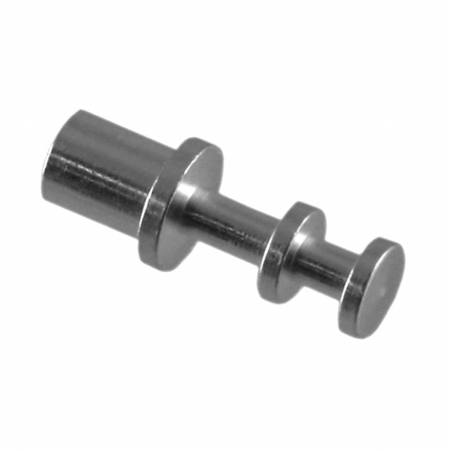
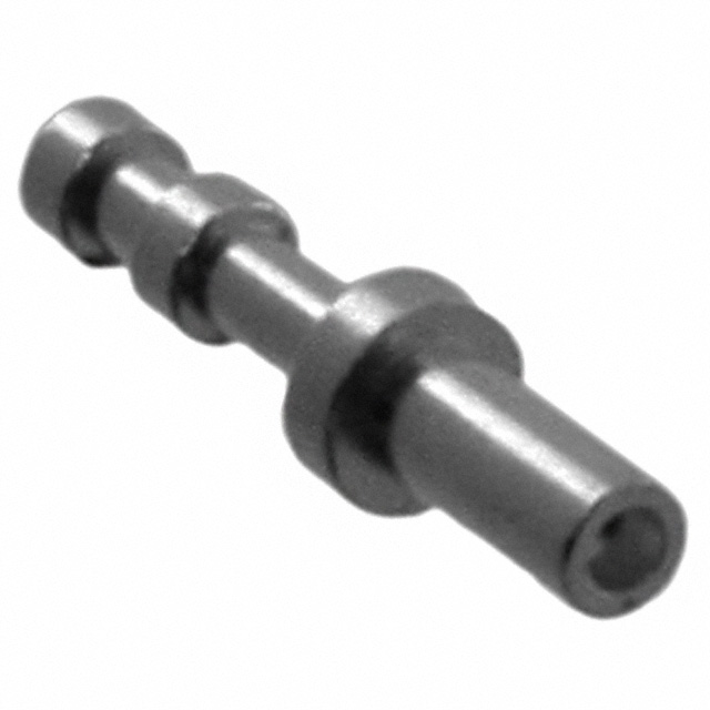
While working on a project recently, I noticed that Digi-key has a product category "Terminals - Turret Connectors". I've never seen connectors like this before, and they don't look like any kind of contact I've seen before. What does the mating connector look like? I can't envision any mating contact that makes any sense for these.

On top of that, they look like they have to be individually machined, which can't be a cost-effective process.

enter image description here

enter image description here

\$\endgroup\$
4
  • \$\begingroup\$ There is no mating connector, you just wrap a wire around it and solder it on. \$\endgroup\$
    – The Photon
    Commented Mar 10, 2019 at 16:44
  • \$\begingroup\$ @ThePhoton So these are more for point-to-point construction I guess? \$\endgroup\$
    – Hearth
    Commented Mar 10, 2019 at 16:45
  • 1
    \$\begingroup\$ You still find them on some RF modules. For example, some LNAs by Minicircuits. \$\endgroup\$ Commented Mar 10, 2019 at 16:47
  • \$\begingroup\$ I used to use them for a ground connection for probes since they're larger than a Keystone 5019 and can accommodate multiple connections easier. \$\endgroup\$
    – Matt Young
    Commented Mar 10, 2019 at 17:04

2 Answers 2

8
\$\begingroup\$

Turret connectors or more commonly Turret terminals are used for to make interconnections between PCB and chassis-mounted components.

Basically these are metal terminals to which wires are connected in a U shape and then soldered to provide strong and reliable connections.

The turret refers to the amount of levels (i.e. the disk like separations) the terminal has. These terminals commonly come in the following types but custom terminals can also be made.

  • Single Turret
  • Double Turret
  • Triple Turret
\$\endgroup\$
5
  • 1
    \$\begingroup\$ So what makes these better than just soldering directly to the board? \$\endgroup\$
    – Hearth
    Commented Mar 10, 2019 at 17:00
  • \$\begingroup\$ Incidentally, sorry to mess up your 1337 reputation score with my upvote! \$\endgroup\$
    – Hearth
    Commented Mar 10, 2019 at 17:00
  • \$\begingroup\$ @Hearth, From the images I found online, I concluded that these terminals were most commonly used on panels instead of PCBs. Hope this helps but a person of that era might be able to explain this better. \$\endgroup\$ Commented Mar 10, 2019 at 17:07
  • \$\begingroup\$ I didn't knew the meaning of 1337, googled it right now. No problem always appreciate an up-vote :) \$\endgroup\$ Commented Mar 10, 2019 at 17:11
  • 1
    \$\begingroup\$ @Hearth, Take a look here, seeing this page, I suspect that turret might be a better option over a straight away connection as directly soldering low-gauge wire might end up ripping the copper layer. Also, joining multiple wires is a lot easier with the help of turret. \$\endgroup\$ Commented Mar 10, 2019 at 17:27
3
\$\begingroup\$

We used them in the 70's for pigtail wire soldering and they are swaged or press fit onto PCBs. Not expensive. They used to be a penny in volume now $0.07. That's inflation and dates me.

The purpose is to provide a strong mechanical joint for stranded wires with 1 wrap around the turret and potted to NASA standards for reliability for strain relief.

This article explains some of the science and MTBF calculations behind moving wire fatigue which is consistent with my experience in production and reliability testing.

Whereas a wire soldered directly to the board lacks the strain relief at the interface. Of course, commercial practice has alternatives, suboptimal, but adequate in their environment.

\$\endgroup\$
7
  • 1
    \$\begingroup\$ Well now I'm curious how they managed to manufacture them so cheaply, as the shape looks like it has to be machined on a lathe... or are they cast in molds somehow? Those protrusions combined with the bottom part apparently being hollow makes them seem kind of complex to manufacture. \$\endgroup\$
    – Hearth
    Commented Mar 10, 2019 at 16:52
  • \$\begingroup\$ Well that's a trade secret, but the cheaper ones are roll hardened CuZn (brass) then annealed or softened to make less brittle then tin plated. I have a retired friend who used to machine the gold connector threaded parts in large batches in the last decade for tidy profits for ARINC-B connectors that made these parts look massive. \$\endgroup\$
    – D.A.S.
    Commented Mar 10, 2019 at 17:06
  • \$\begingroup\$ Our techs had NASA soldering manuals thicker than the bible and koran put together. imagine that. These included photos of idea pigtail solder joints for 10 lb pull tests on wires. But being hard brass, they still bend before breaking. THe wires soldered in PCB's have a discontinuity in stress/strain making them prone to vibration failures. ( do I need to explain that?) \$\endgroup\$
    – D.A.S.
    Commented Mar 10, 2019 at 17:08
  • \$\begingroup\$ @SunnyskyguyEE75, found this page which relates to the things you have mentioned. \$\endgroup\$ Commented Mar 10, 2019 at 17:21
  • 2
    \$\begingroup\$ sorry @MattHusz it wasn't on archive.org either. basically 3 points. 1) strain relief should be used on joints then 2) wires that move/vibrate be tied or glued down and 3) move with some actuator , the wire should be guided to move in axial direction with large radius not in the radial direction which will fail prematurely \$\endgroup\$
    – D.A.S.
    Commented Jul 3, 2022 at 19:27

Your Answer

By clicking “Post Your Answer”, you agree to our terms of service and acknowledge you have read our privacy policy.

Not the answer you're looking for? Browse other questions tagged or ask your own question.