5
\$\begingroup\$

This is a follow-up of that question.

The only reason I've got 8 transistors on that schematic is efficiency. I'm now trying to figure out whether switching losses are making it pointless to have so many transistors.

Theoretically only 1 of those transistors will be enough to run the motor, but power lost in the DS path is current squared times resistance so at 30A that's:

$$ 30^2*0.025 = 22.5 W $$

That's not a small loss and will probably require a huge heat sink. Contrary, if I put 8 transistors in parallel as in the schematic, each resistor will carry 30/8 = 3.75A, which will result in a total loss of:

$$ 3.75^2*0.025*8 = 2.81 W $$

However switching losses will increase 8 times. The answer to the other question has helped me determine that if I want to switch at 100ns the current needed to energize the gate will be 350mA, so times 8 (transistors) that's 2.8A or 14W, which is getting close to the loss with just 1 transistor. But thinking about it, 350mA is not consumed constantly rather only during gate energizing, which lasts 100ns. At a frequency of 22khz that's obviously 22k switches per second, times 100ns equalling 2.2ms of total time draining current per second.

Thus, the real power "wasted" in switching gates will be:

$$ 14 * 0.0022 = 0.031W $$

Which is substantially better than 14W, so having more transistors is clearly the better choice. Unfortunately I'm nowhere near an electrical engineer and I'm completely uncertain about my theory above, that's why I'm posting this question.

EDIT:

For future readers, since the comments on the answer are quite long: It turned out switching losses are not at all what I thought they were, what I was referring to as switching losses is apparently gate driver losses. The real power wasted is the sum of resistive losses and real switching losses, which in my case turned out to be optimal at 3 transistors, in theory.

\$\endgroup\$
4
  • \$\begingroup\$ Are you still using the IRLZ44N? What's your gate drive voltage? \$\endgroup\$ Commented Dec 24, 2022 at 17:31
  • \$\begingroup\$ @JonathanS. Yes, gate drive voltage has increased to 5V though. \$\endgroup\$
    – php_nub_qq
    Commented Dec 24, 2022 at 17:37
  • 2
    \$\begingroup\$ Have you considered using a different MOSFET, like the IRLB3036PBF for example? It costs $5 and has 10x lower on-resistance at only twice the gate charge. You'd only need a single one of them. MOSFET technology has come a long way since the IRLZ44N was introduced. \$\endgroup\$ Commented Dec 24, 2022 at 17:37
  • \$\begingroup\$ @JonathanS. that's some useful information, I might as well. But I'm still interested in finding out whether my calculations make sense. \$\endgroup\$
    – php_nub_qq
    Commented Dec 24, 2022 at 17:39

1 Answer 1

6
\$\begingroup\$

Ideally, you want conduction losses to equal switching losses. But conduction and switching losses change with load (ala duty cycle) so the crossover point where switching losses = conduction losses depends on the operating point you choose.

Don't forget that MOSFET resistance rises with temperature. You should be using that value obtained from a graph in the MOSFET datasheet You need enough gate drive.

You already know how to calculate conduction losses. Calculating switching losses is more difficult and depends on your gate drive. That means if you do not have enough gate drive then more parallel MOSFETs will hurt more than it helps.

There's a lot to be said about how to calculate switching losses and I don't understand a lot of it (modelling MOSFET and all that junk), and frankly I've never had calculations match up with real world results so I am probably not doing something correctly, but I use a simplified calculation anyways since it's something to go by.

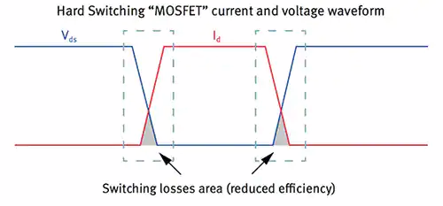
The calculation I use is the one that assumes that when the MOSFET turns on and off the Vds and Ids ramp in linearly opposite directions at equal rates between 0% and 100% voltage and current. So a more symmetrical version of this. An actual switching waveform looks a lot messier with lots going on, but whatever.

enter image description here https://www.digikey.com/en/articles/a-review-of-zero-voltage-switching-and-its-importance-to-voltage-regulation

The rise or fall time is assumed to be the same and is approximated using Q = IT, where Q is the MOSFET total gate charge and I is the gate driver current. So \$t_{rise/ fall} = \frac{Qgs}{I_{gate.driver}}\$

The switching loss during one transition is the Vds multiplied by the Ids during that ramping. So on a graph it's a triangular shape which works out to be power.

Since we are assuming the voltage and current rise or fall between 0% and 100% and equal rates then one way to calculate the power lost in one transition is to multiply the average voltage by the average current during this transition period (which is half the value of each): \$P_{one.switch}=\frac{1}{4}V_{ds}I_{load}\$

Then to get the total switching power lost you do:

\$P_{switching} = P_{one.switch}(t_{rise}+t_{fall})f_{PWM}\$

Or you can calculate the energy lost during one transition geometrically from the area under the power graph over the switching region obtained by multiplying the voltage and current waveforms multiplied together. Then divide that by the PWM period to get the power.

ADDENDUM: The 0.031W calculated by the OP is the power used to charge and discharge the MOSFET gates. We don't normally care about this when calculating switching loss because the value is so miniscule compared to the power being burned off by the MOSFET as in transition between on and off states. But for interest sake, the energy in one charge or discharge would be calculated as \$\frac{1}{2}CgsVgs^2\$, then averaged over the PWM period to get the power. Neglecting little annoyances such as the gate resistances, losses in the gate driver components and the way gate capacitance varies with Vgs.

  • Full on = low Vds x high Ids = low loss.
  • Full off = high Vds x low Ids = low loss
  • But when switching you are in between the same way a linear regulator is = lots of heat.
\$\endgroup\$
14
  • 1
    \$\begingroup\$ I'm picking up that there's something I'm completely unaware of. As switching losses I'm addressing energy used to energize the gates, there's also a switching loss in the DS path? \$\endgroup\$
    – php_nub_qq
    Commented Dec 24, 2022 at 17:47
  • 2
    \$\begingroup\$ @php_nub_qq It does take energy to charge and discharge the gates but that is negligible in most circuits compared to the massive amounts of power being burned when the transitions between on and off. Full on = low Vds x high Ids = low loss. Full off = high Vds x low Ids = low loss. But when switching you are in between the same way a linear regulator is = lots of heat. When people talk about switching loss of MOSFETs, that's what they are talking about, not the tiny amount of energy used to charge and discharge the gate capacitance which is basically just the power consumption of gate driver \$\endgroup\$
    – DKNguyen
    Commented Dec 24, 2022 at 17:56
  • \$\begingroup\$ I suppose that's why the accepted answer on the linked question suggested a short as possible switch time. But by you saying the energy needed to charge the gates is negligible I'm assuming that my thoughts were correct, which was what I was aiming to learn with this question. Unfortunately I used poor terminology, apparently. \$\endgroup\$
    – php_nub_qq
    Commented Dec 24, 2022 at 17:59
  • 1
    \$\begingroup\$ @php_nub_qq Then you do what I am describing. And yes there is also a switching loss in the DS path in addition to the conduction (resistive) loss and in doing so you usually neglect the energy used to energize the gates since it is miniscule compared to the heating the MOSFET experiences while transitioning. \$\endgroup\$
    – DKNguyen
    Commented Dec 24, 2022 at 18:12
  • 2
    \$\begingroup\$ @php_nub_qq It's just kind of something to go by. It's part of the reason I used a simplified switching waveform for the calculation and not something more complex. Also note I made some corrections to the equations. There are other calculation methods and spreadsheets using other methods supplied by vendors. Not sure if they are more accurate or not but they take different (and confusing) parameters. They didn't seem any more or less accurate to me but maybe I was using them incorrectly. \$\endgroup\$
    – DKNguyen
    Commented Dec 24, 2022 at 18:23

Your Answer

By clicking “Post Your Answer”, you agree to our terms of service and acknowledge you have read our privacy policy.

Not the answer you're looking for? Browse other questions tagged or ask your own question.