13
\$\begingroup\$

I have a small signal transformer with values as in the below schematic (the simulate button works well to see the AC response). The values are measured and the simulated AC response agrees sort of well with the actual behavior. In case anyone wonders about the large value of C1: It is the capacitance from two antiparallel protection diodes.

The loss resistances R2/R3 turned out so high that the signal essentially isn't attenuated at all (that's good... don't get me wrong). I expected them to be "lower" (more lossy) because of the highly conductive core material.

The core is made from VITROPERM 500F (see tables at the bottom of this page for parameters).

schematic

simulate this circuit – Schematic created using CircuitLab

The core loss mechanisms in transformers that I am aware of are:

  • magnetic hysteresis losses, which is the dominant loss mechanism for high resistivity ferrites up until very high frequencies
  • eddy current losses which should be rather large in VITROPERM, as its resistivity is only about 100x that of copper (5-6 orders of magnitude lower than usual ferrites)

So VITROPERM should be really lossy even at intermediate frequencies due to eddy losses, and indeed the company VAC seems to be proud of the high lossiness of VITROPERM for applications such as common-mode chokes. For example Fig. 7 in that document shows how VITROPERM is already very lossy in the dozens of kHz: enter image description here
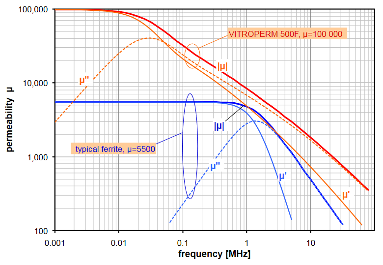
Judging from that graph, I would expect that the inductive behavior of the core essentially gives way to a dissipative one already at ~40 kHz and that magnetic coupling between primary and secondary should be greatly attenuated as a result.

Still I see two things which I guess shouldn't happen: I could also see the resonance of the leakage inductance L1 with the secondary capacitances at ~250 kHz. And for lower source impedance R1, I could also transmit much higher frequencies, 100s of kHz, without attenuation.

So why is it, that metallic transformers are considered way too lossy for SMPS, but this transformer with a metallic core, transmits just fine up until 250 kHz?

\$\endgroup\$
5
  • 1
    \$\begingroup\$ I don't see how anyone can answer about the values of R2 and R3 with the information you have presented. \$\endgroup\$
    – Andy aka
    Commented Jan 5, 2023 at 10:30
  • 2
    \$\begingroup\$ @Andyaka well I am not looking for a quantitative "solution" for R2/R3. I am just puzzled, why this transformer works at all at frequencies, well beyond where its core material becomes profoundly dissipative. A lower R2/R3 would be just a schematic concept that would express such lossiness. I will reformulate that section. \$\endgroup\$
    – tobalt
    Commented Jan 5, 2023 at 10:35
  • 2
    \$\begingroup\$ Eddy current losses don't stop it operating as a transformer. I've used pieces of ferrite at hundreds of MHz to improve coupling of signals from one coil to another coil and ferrite losses at hundreds of MHz are just as bad (if not worse) than vitroperm at your frequency range. \$\endgroup\$
    – Andy aka
    Commented Jan 5, 2023 at 11:34
  • 1
    \$\begingroup\$ @Andyaka I always have that mental picture in my head that Todd Hubing nicely demoes here: youtube.com/watch?v=_Zq6qiuuINE&t=375s The conductive shield inserted between a sender and receiver coil, generates an opposing magnetic field (eddy currents) reducing the coupling very severly - the essence of shielding. Could you maybe add a thought of why this might be different (or less important) in a transformer ? \$\endgroup\$
    – tobalt
    Commented Jan 5, 2023 at 12:11
  • 1
    \$\begingroup\$ That video is inapplicable as far as I can tell. The eddy current losses in the vitroperm take power from the source but, do not stop the magnetic field being coupled to the secondary. Look at the equivalent circuit for a transformer; if leakage losses are small (as you would expect with a transformer) providing the source can still apply the same voltage, the coupling of that voltage to the output via the turns ratio is unaffected. \$\endgroup\$
    – Andy aka
    Commented Jan 5, 2023 at 12:36

4 Answers 4

15
\$\begingroup\$

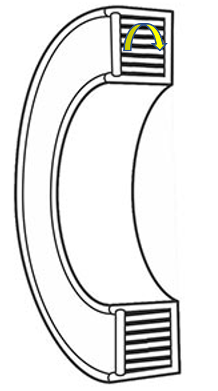
Take a look at this cross section of a tape-wound core from https://www.magneticmetals.com/products-materials/tape-wound-toroidal-cores :

enter image description here

I have added the arrow to show the direction of the eddies that will result from your windings. Notice that the eddy currents must cross many layers of the Vitroperm tape. Each layer of tape is insulated from its adjacent layers as it is wound on, so the eddy path is interrupted.

As you go up in frequency, the eddies get smaller until eventually you can have significant eddies within the thickness of a single layer of tape. But, tape-wound cores use tapes with thicknesses of less than a mil; 0.5 mil thicknesses are common (0.0127 mm). So, the tape reduces eddy currents in the same fashion as laminations in larger transformers, and their upper frequency is dependent on the thickness of the tape.

\$\endgroup\$
7
  • 3
    \$\begingroup\$ Aha! I found no mention anywhere that these cores used an insulating layer. Would surely make sense for a signal transformer core. On the other hand an attenuating choke, such as a CMC, would probably do better without the insulating tape. Do you know if the insulating tape layer is always used ? Seems a bit hard to tell from the outside. \$\endgroup\$
    – tobalt
    Commented Jan 5, 2023 at 14:43
  • 2
    \$\begingroup\$ I sure don't! Tape-wound cores were more prevalent in the days when switched-mode power supplies all operated below 100 kHz, and circuit design has progressed to where ferrites have supplanted them in many applications. The entire idea of the tape-wound approach is to reduce losses, so I don't think you would use this approach for an intentionally lossy core. \$\endgroup\$ Commented Jan 5, 2023 at 14:53
  • 2
    \$\begingroup\$ @tobalt given the heading "Common-mode chokes and tape-wound cores" in that PDF you found, I'm guessing not :) \$\endgroup\$
    – hobbs
    Commented Jan 5, 2023 at 18:17
  • 1
    \$\begingroup\$ As I understand it, coatings include surface oxide (more so with traditional transformer iron), varnish or resin, or maybe not much at all. Note that contact resistance between layers would reduce the overall permeability (it manifests as a shorted turn in parallel with the magnetizing current) -- so CMCs are also best with insulation here. \$\endgroup\$ Commented Jan 6, 2023 at 2:34
  • 1
    \$\begingroup\$ @TimWilliams could you elaborate on that shorted turn argument ? I dont get it. the DC (LF) permeance of the core is unaffected if the type is insulated or not. What is affected is the AC losses because of eddy currents. IMO the real permeability (µ') shouldn't be affected either. \$\endgroup\$
    – tobalt
    Commented Jan 6, 2023 at 7:16
9
\$\begingroup\$

Vitroperm is not a metallic material, it's an nanocrystalline alloy (ultra fine grains of FeSi are embedded in Nb and Cu additives). Transformers made of this type of materials are commonly used in SMPS

\$\endgroup\$
8
  • \$\begingroup\$ Thanks, I didn't know that they are indeed used in SMPS. I thought only ferrites were. And why do you think that metals can't be nanocrystalline or amorphous ? "Metal" says nothing about the material microstructure. It does say something about conductivity though. And the conductivity of vitroperm surely qualifies it as a metal. \$\endgroup\$
    – tobalt
    Commented Jan 5, 2023 at 14:25
  • \$\begingroup\$ More than "nanocrystalline" the important part is "alloy", specially Si and B are nonmetallic elements used in this type of alloys \$\endgroup\$
    – Ken Grimes
    Commented Jan 5, 2023 at 15:00
  • 3
    \$\begingroup\$ Steel also contains carbon and I guess you would consider steel a metal, right ? Most metals, you use everyday are alloyed with "nonmetallic" elements. That doesn't make them nonmetals. VAC themselves call the VITROPERM alloy a metal, if you look at Figure 1 caption in the document linked in the question. \$\endgroup\$
    – tobalt
    Commented Jan 5, 2023 at 15:04
  • 1
    \$\begingroup\$ It is a metallic material. It's a metallic glass with nano-sized crystals formed by annealing. The crystallinity does not define the metallicity; and it's not a composite or matrix formed from conventional (e.g. FeSi) particles. \$\endgroup\$ Commented Jan 6, 2023 at 2:23
  • 1
    \$\begingroup\$ Transformers are commonly used as common mode chokes, for filtering. CMCs may be defined as transformers, but aren't often sold that way so it may be worth clarifying that. They are rarely used for switching power conversion, but have niche applications for signal conversion (ye olde ISDN made excellent use of them). \$\endgroup\$ Commented Jan 6, 2023 at 2:26
4
\$\begingroup\$

TL;DR

From a quick research I made on the Internet, the explanation may lie in the material being made of nanoparticles.

Explanation

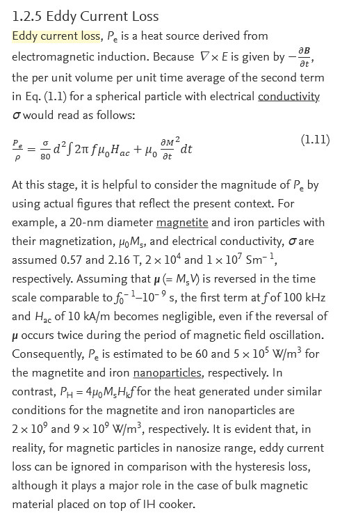
Although eddy current losses in bulk magnetic materials increase with frequency, as stated in Wikipedia here, from an excerpt from a book here we infer that nanoparticles behave differently (copy-pasted as image because of lots of formulas):

enter image description here

Source: "Design Criteria of Thermal Seeds for Magnetic Fluid Hyperthermia From Magnetic Physics Point of View"; Hiroaki Mamiya, Balachandran Jeyadevan, in "Nanomaterials for Magnetic and Optical Hyperthermia Applications", 2019


Note the last sentence (emphasis mine):

It is evident that, in reality, for magnetic particles in nanosize range, eddy current loss can be ignored in comparison with the hysteresis loss, although it plays a major role in the case of bulk magnetic material placed on top of IH cooker.

This would explain why, that material behaves like it is advertised.

The fact that the material is also manufactured in tiny sheets would further decrease eddy current losses, as lamination do in good old mains transformers with EI-core made of FeSi alloy.

EDIT

Further research led me to this article:

The influence of Fe nanoparticles on microstructure and magnetic properties of Fe-6.5wt%Si soft magnetic composites

excerpt (emphasis mine):

Abstract

The effect of Fe nanoparticles with mass fraction of 0-7 wt% on the microstructure and soft magnetic properties of the Fe-6.5 wt%Si soft magnetic composites (SMCs) was investigated. The results show that the pores between Fe-6.5 wt%Si powders can be effectively filled by Fe nanoparticles, thereby correspondingly increasing the density of the SMCs. At the same time, the magnetic permeability of the SMCs mixed with different mass fraction of Fe nanoparticles has improved significantly and exhibits good frequency stability compared with the absence of Fe nanoparticles. It also reveals that the addition of 1 wt% Fe nanoparticles can reduce the eddy current loss of the SMCs by decreasing its intra-particle eddy current loss. When the addition of Fe nanoparticles is 3 wt%, the SMCs exhibits good magnetic properties with high magnetic permeability (increased by 24%) and relatively low core loss.

which further support my hypothesis.

\$\endgroup\$
11
  • \$\begingroup\$ in that discussed compound, the bulk conductivity is severly limited by the magnetite. But for vitroperm, the bulk conductivity is given as ~1 MS/m, which includes conduction through all its microstructure (crystals and amorphous phases). So surely the eddies in vitroperm are much stronger than in that discussed iron-magnetite compound. \$\endgroup\$
    – tobalt
    Commented Jan 5, 2023 at 15:53
  • \$\begingroup\$ @tobalt They also mention iron nanoparticles, and their conclusion is the same. It's not a definitive answer, but it shows that if conduction takes places in nanoparticles their dimension plays a role. \$\endgroup\$ Commented Jan 5, 2023 at 15:59
  • \$\begingroup\$ @tobalt And the bulk conductivity is most probably the DC conductivity. Skin effect and proximity effect may change the picture. \$\endgroup\$ Commented Jan 5, 2023 at 16:00
  • 1
    \$\begingroup\$ @tobalt see my edit. \$\endgroup\$ Commented Jan 5, 2023 at 16:07
  • \$\begingroup\$ Yes it could be that the skin effect is less severe in a nanocomposite material indeed \$\endgroup\$
    – tobalt
    Commented Jan 5, 2023 at 16:07
4
\$\begingroup\$

Simple: the magnetizing inductance doesn't play much role in the LL-Cs resonance. Core loss is effectively in parallel with the magnetizing current, i.e. the primary or secondary inductance. If the magnetizing current is small enough -- you really don't care what phase it has!

schematic

simulate this circuit – Schematic created using CircuitLab

This is a typical 2nd order nonideal transformer model. Rp/Rs model DC resistances, Cp/Cs the total winding self-capacitances (there will also be some across the isolation barrier, between the respective ends of the windings), LLp/LLs the leakage inductance (for \$k \rightarrow 1\$, we can approximate it by lumping it all to one side; at lower \$k\$, we might want to use both), Lm the magnetizing inductance, and Rm its loss. T1 is an ideal transformer with ratio N2/N1.

As a first order model, core loss can be represented simply as a resistance in parallel with the magnetizing inductance.

This approach is also the trick with RF transformers: it's hard to find any material that's meaningfully inductive (not loss dominant) at 100s of MHz, but simply using enough turns that the magnetizing impedance is several times the system impedance (i.e., say 200 ohms compared to the 50 ohm transmission line it connects to) gets you there with <1dB insertion loss, and if that's good enough, who cares, eh?

It may be worth noting that fringing fields and leakage flux (the flux literally leaking out of the core, into space -- not necessarily just that measured between windings) flow thru-plane in these materials (high-mu amorphous/nano. materials are made in strip form only), so will encounter high losses. This is really only a problem with uneven windings, or around air gaps.

Uneven windings includes the sectoral wind on a toroid, such as commonly used for common mode chokes. In that case, the differential mode will have higher losses. (But, that's not at all a problem in that application; it might be valuable if anything.)

These materials are also available in cut C cores, which can be air-gapped for inductor use (energy storage). This isn't useful at high frequencies for this reason; but the low losses at mains frequency may still make them useful (if a rather expensive choice).

\$\endgroup\$
1
  • \$\begingroup\$ (Thanks for the comments on the other replies, too). I think you are right about the resonance of the leakage inductance with the secondary winding capacitance not requiring the core. Not sure, it explains why the transformer transmits fine up to 250 kHz given a low enough source impedance. I think your 2nd+3rd sentence ("Core loss...it has!") are important but I dont fully get it. Could you expand that bit a little bit ? \$\endgroup\$
    – tobalt
    Commented Jan 6, 2023 at 7:22

Your Answer

By clicking “Post Your Answer”, you agree to our terms of service and acknowledge you have read our privacy policy.

Not the answer you're looking for? Browse other questions tagged or ask your own question.