1
\$\begingroup\$

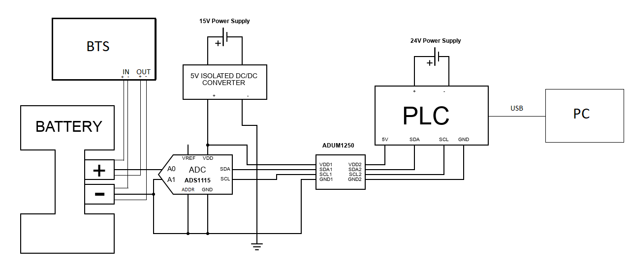
I want to read a DC voltage from a battery with 0.1mV resolution or better and send the value to a PLC based in Arduino Mega. I selected an ADS1115 (datasheet here) which has enough resolution to do that. I already created a question in the past (this one), which was very helpful as I improve the reading a lot by doing 2 things: connecting the ground to the negative pole of both the battery/ADC input (to assure common ground for differential mode), and isolating the digital part (to avoid digital currents getting to the ADC input by ground loops). However, I still have some ocassionaly oscilations in the reading as I will explain in detail. The final set-up after the answers from the previous question looks like this:

enter image description here

ADS1115 is from Adafruit which break out board is mounted on a breadboard. ADUM1250 is used in its evaluation board and connected to the breadboard. Last but not least, the BTS is a battery test system connected to the battery which has two functions:

  1. Battery cycling. It injects a constant current (100 mA) in the following way: it starts injecting +100 mA to charge the battery, and after some minutes it injects -100mA to discharge the battery (and the process repeats several times). This is done by OUT connection, using both positive and negative cables to the battery poles respectively.
  2. DC voltage measurement. The BTS also provides an stable and correct measurement with no oscillations (using IN connection, also using positive and negative), which is used as a reference to compare with my ADC measurement. I also did the measurements with a multimeter which matches perfectly the BTS value. So it is clear that the problem is in the ADC reading.

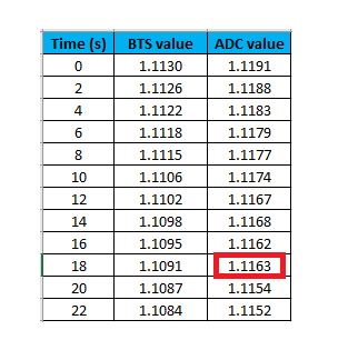
My feeling is that there is some voltage drift entering the ADC. To give more tips about the oscillation that maybe can help to identify the issue, the following table shows an example of the it compared with the BTS/multimeter reading. ADC datarate is set to the maximum value (860 samples per second) and then the PLC stores the last value in a variable and prints it every 2 seconds to a file:

enter image description here

These values are during a discharge cycle (voltage always decreases along time). As the time goes on (epochs every 2 seconds), BTS always reads an smaller value (-0.0004V or -0.0003V compared with the previous one). However, the ADC occasionally reads +0.0001V (epoch marked in red color), which is a larger value than the previous one, and this mess up completely my further computations. I need a clear signal, it is not a solution for me to filter by software.

What could be the cause for this ocassional oscillations? They always happen in the opposite direction of the cycling: if the battery is being discharge, voltage goes up, but in the battery is being charge, the voltage goes down. Besides, there is an offset around 60mV on the ADC readings compared with the reference readings which I cannot explain. This offset does not affect my computations but maybe gives some clue of the problem.

I tried to replace the ADS1115 by an ADS1219 but the results were the same so it seemts that something in the ADC inputs or outputs is still affecting.

Find also the code related with the ADC reading and value printing. One timer interrupt is used to do an average of 4 values (FIR filter) and other time interrupt to print the value every 2 seconds:

#include <TimerOne.h>
#include <TimerThree.h>
#include <Wire.h>
#include <Adafruit_ADS1X15.h>

const int AVGNUMELEM = 4;
float  ADCValue ;
float arrayAvg[AVGNUMELEM];
float avg = 0;
int counteravg = 0;
const float scalefactor = 0.0001250;//ref 4V
const int PCSERIALSPEED = 9600;
const int MILLISINSEC = 1000;
//2 seconds
const long TIMER1TIME = 2000000;
//0.5 seconds
const long TIMER3TIME = 500000;
// Pin output of the PLC
int DIGITALOUTPUT = 42;

Adafruit_ADS1115 ads1115_battery;

// Timer called every 0.5 seconds
void ISR_Store4values() {

  if(counteravg < AVGNUMELEM){
    arrayAvg[counteravg] = ADCValue;
    counteravg ++;
  }
  else
  {  
    for(int i = 0; i < (AVGNUMELEM-1); i++){
      arrayAvg[i] = arrayAvg[i + 1];
    }
    arrayAvg[(AVGNUMELEM-1)] = ADCValue;
  }
}

// Timer called to compute the average every 2 seconds
void ISR_PrintEvery2s() {
 
  avg = 0;
  for(int i = 0; i < AVGNUMELEM; i++){
    avg = avg + arrayAvg[i];
  }
  avg = avg / AVGNUMELEM;

  Serial.print(avg,4);
}

void setup() {

  Timer1.initialize(TIMER1TIME);
  Timer1.attachInterrupt(ISR_PrintEvery2s); 

  Timer3.initialize(TIMER3TIME);
  Timer3.attachInterrupt(ISR_Store4values);

  pinMode(DIGITALOUTPUT,OUTPUT);

  Serial.begin (PCSERIALSPEED);

  ads1115_battery.begin();
   
  if (!ads1115_battery.begin()) {
    Serial.println (F("Error when init ADC"));
    while (1);
  }

  ads1115_battery.setGain(GAIN_ONE);

  // Data rate 860 sps  https://github.com/RobTillaart/ADS1X15
  ads1115_battery.setDataRate(7);

}

void loop() {

  ADCValue = scalefactor * ads1115_battery.readADC_Differential_0_1();

}
\$\endgroup\$
21
  • 2
    \$\begingroup\$ Are these single ADC measurements made once per two second? You use the words epochs and, I think you mean samples? Have you done an error budget calculation for the ADC? Please link the data sheet of the ADCs. What ADC voltage reference are you using? \$\endgroup\$
    – Andy aka
    Commented Mar 18, 2023 at 12:01
  • 1
    \$\begingroup\$ What about the other inputs on the ADC1115? How much settling time do you provide for the multiplexer? \$\endgroup\$
    – Andy aka
    Commented Mar 18, 2023 at 12:07
  • 2
    \$\begingroup\$ Have you tried replacing the battery with an accurate fixed value voltage source and see if you still have the problem? In other words; divide and conquer or, deal with the errors from each sub-system rather than trying to debug the whole system. \$\endgroup\$
    – Andy aka
    Commented Mar 18, 2023 at 12:24
  • 2
    \$\begingroup\$ I think the code is just not interrupt safe and copying around floats in a couple of timer interrups is just very awkward way of trying to achieve what you want. Fix the code so that you know the code is not causing the issues you are seeing. It may be a code problem and not a problem in hardware. \$\endgroup\$
    – Justme
    Commented Mar 18, 2023 at 12:55
  • 2
    \$\begingroup\$ @bardulia It depends what your main code does. But you seem to be doing all the things you should never do in interrups, such as printing. Unless you know how the MCU handles interrupts, and how the mystery Arduino code modules function, and what you can do or not in interrupts, you should not do anything more that you have to in interrupts. And I have never written any Arduino code in my life and I would not use any Arduino code on AVR so I have no clue what you should do. \$\endgroup\$
    – Justme
    Commented Mar 18, 2023 at 15:57

2 Answers 2

4
\$\begingroup\$

As suspected, it is a code problem.

The interrupts can happen at any time, including in the middle of when the main code has halfway updated the float variable. As the AVR is an 8-bit MCU, writing any variable wider than 8-bit can be interrupted when only part of it is written, unless you make sure to guarantee atomicity.

And depending on how your Arduino libraries want to handle interrupts, interrupts may also be interrupted by another interrupt, so each time you want to use Arduino libraries, you need to figure out how they work, or you don't know how they work or should be used.

The use of two interrupts is rather useless. If you have one interrupt happening every 0.5 seconds and another one happening every 2 seconds, you could just check use one interrupt every 0.5 seconds and you know that every fourth time 2 seconds has passed so you could just that code on every fourth interrupt.

Usually complex and long operations are avoided in interrupts. There is usually very limited amount of things you can do in interrupts, which should also be figured out what those are. For example, if you ever used print in main loop, you would not be able to use it in an interrupt. Unless you know how it works and it is possible to do so. It might crash or just write prints happened in interrupt in the middle of a print from main code. It may or may not be re-entrant. It might not even work when called from interrupts, but again that is also a thing which needs to be known from the programming environment you are using.

Whar you could do is to just set a flag variable that 0.5 seconds has passed in the interrupt. Then in main code check if flag is set, read ADC value, and when four values has been read, average them, convert to float and print.

As a final optimization, why bother using floats as they are very slow on 8-bit MCUs. Your scale factor is just 1/8000. You can just just use ADC values directly as integers, and if you divide by 8, you have the voltage in units of millivolts. Or, multiply the ADC value by 125, and the voltage is in units of microvolts. Of course this is assuming you really have 4.000 volt reference. The internal reference is 4.096V which makes calculations even easier.

\$\endgroup\$
2
  • 1
    \$\begingroup\$ I am the first interested in this type of solution, as I was having no more alternatives for the hardware part. I will rewrite the code then and come back here for the results. Many thanks. \$\endgroup\$
    – bardulia
    Commented Mar 18, 2023 at 19:47
  • \$\begingroup\$ I have thought the following: to remove the two timer interrupts and then use an RTC (I have a similar PLC with this functionality) to print values every 2 seconds. Finally I would discard the 4 value average as probably with the new code and the final hardware setup I won't need it anymore. What do you think?. \$\endgroup\$
    – bardulia
    Commented Mar 19, 2023 at 18:57
1
\$\begingroup\$

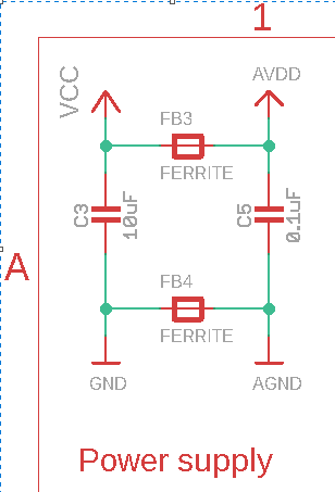
Here is your ADS1115 breakout board power supply:

enter image description here

Here are the GND and AGND pins of the breakout board.
(GND and VCC) should be wired to the power supply and (AGND & AVDD) wired to the main system.

\$\endgroup\$
4
  • \$\begingroup\$ That is very useful, thanks a lot. I will try the new set-up and come back here to post the results. \$\endgroup\$
    – bardulia
    Commented Mar 19, 2023 at 19:05
  • \$\begingroup\$ I have finally found a problem with my ADS1115 from Adafruit, it is an older revision from the one on the website and the breakout board is different: curiously it does not have AGND/AVDD pins. I am going to contact Adafruit about this, but I think that probably I need to buy the new revision. \$\endgroup\$
    – bardulia
    Commented Mar 23, 2023 at 10:38
  • 1
    \$\begingroup\$ You can add 2 pins (AGND and AVCC) and try it ? \$\endgroup\$
    – Antonio51
    Commented Mar 23, 2023 at 11:04
  • \$\begingroup\$ Ok! Anyways I have just ordered the new revision and it is on its way so I will try both. \$\endgroup\$
    – bardulia
    Commented Mar 23, 2023 at 11:41

Your Answer

By clicking “Post Your Answer”, you agree to our terms of service and acknowledge you have read our privacy policy.

Not the answer you're looking for? Browse other questions tagged or ask your own question.