0
\$\begingroup\$

When looking for a gate driver to drive a FET with 65nC gate capacity at 10V with a frequency of 100 Hz I found the VOM1271. Unfortunately it seems like with such a high gate capacity it is impossible for this part to switch fast enough, I calculated the switching time to be over 1 millisecond. So I was wondering if I could use the VOM1271 as an always on isolated power supply to constantly charge a capacitor and then just put an isolated gate driver next to it to control the FET?

Does that sound feasible for such a low switching frequency?

\$\endgroup\$
12
  • \$\begingroup\$ "to switch fast enough" -- how fast? This seems to be your assumption, but what justification could you provide to support it? Examples: device and load ratings, allowable power dissipation, required efficiency, minimum pulse width, etc. \$\endgroup\$ Commented Jul 18, 2023 at 14:38
  • \$\begingroup\$ There are MOSFETs with much more than 65nC of gate charge, and they can be switched very quickly (microseconds) as long as a suitably high-current driver is used (Amperes of current.) Could you expand on exactly how the VOM1271 is being driven by showing a schematic? \$\endgroup\$
    – rdtsc
    Commented Jul 18, 2023 at 14:45
  • \$\begingroup\$ @rdtsc The VOM1271 is only able to supply about 50uA though. That's why I wanted to use a faster driver, but I need to supply an isolated voltage for it. \$\endgroup\$
    – Jenny
    Commented Jul 18, 2023 at 14:50
  • \$\begingroup\$ Calculate how much power or current you need to switch 65 nC at 100 Hz and 10 V. Can the VOM1271 supply it? As @rdtsc said, it will be easier to find a different MOSFET. \$\endgroup\$
    – winny
    Commented Jul 18, 2023 at 14:57
  • \$\begingroup\$ @TimWilliams This is for an inverter circuit, I need it to switch as fast as possible to keep the THD low. It will be 50% on and 50% off from a 50 Hz sine wave. I can "wait" until it is fully switched before supplying voltage to the circuit to reduce switching losses, but 1 millisecond is a little too long. Something in the 10uS range would probably be my goal. \$\endgroup\$
    – Jenny
    Commented Jul 18, 2023 at 14:59

1 Answer 1

1
\$\begingroup\$

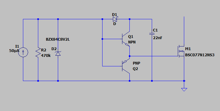
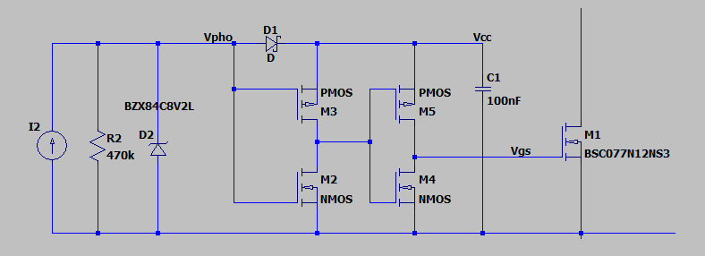
You can improve the speed with an auxiliary capacitor, charged from the photovoltaic driver and a classic transistor output. It needs some ms to charge, so before starting, you should send a pulse train, and get enough voltage to be able for switching the power MOSFET. Once it is charged, you can output 100 % of the time without any additional power supply. The VOM1271 driver is simulated by a current source, resistor and zener. enter image description here EDIT: It is possible to do with MOSFET, but to keep signal high 100% of the time, you need to invert twice. With a single stage, you will not have power to activate the gate. enter image description here
Also, if it is possible to connect a capacitor (like a snubber) at the power MOSFET, then you can get a axiliary supply to speed up the gate switching. The initial pulses will be low speed changing, but after some cycles you will charge the auxiliary supply, and switching on the power MOSFET will be faster. The values of this components should be ajusted for the power voltage and switching frecuency. enter image description here
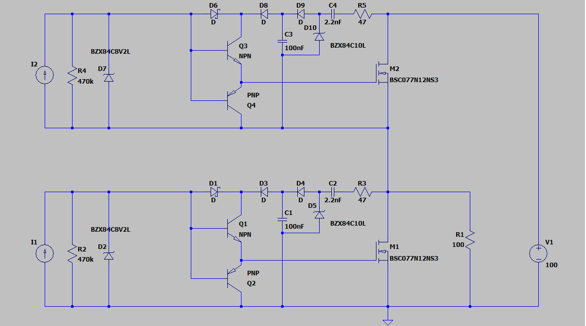
In simulation at 10 ms cycles, green signal is the gate voltage, blue signal is capacitor supply voltage. See difference between rise time of the first and last gate pulses.

enter image description here

In case you cannot wait these ms, you can use a floating power supply.

\$\endgroup\$
4
  • \$\begingroup\$ Thanks, the first option looks really good! I would assume that instead of using bipolar transistors I could also use a P and N-Channel FET there? What exactly do you mean by "you should send a pulse train"? I was thinking about just constantly turning it on to allow the capacitor to charge, then turn it off again and start normal operations then. \$\endgroup\$
    – Jenny
    Commented Jul 24, 2023 at 11:42
  • \$\begingroup\$ If you use P and N channel , I think you will get a inverted signal. That is an issue if you want a 100% output (no power available), but will work if you are always switching. Regarding second question, you are right, first send some pulses and charge capacitor. \$\endgroup\$
    – Bravale
    Commented Jul 24, 2023 at 15:24
  • \$\begingroup\$ I tried it using the inverted method as I will be constantly switching and if I stop switching I will have time to charge it up again before starting operations again. However, on the first low-pulse both FETs are conducting at the same time which discharges the capacitor immediately. I am not yet sure why that is though. I have modeled my voltage source as an actual 9V voltage source with a series resistance of 200000 Ohms, that might not be accurate for the low-pulse switching speed. \$\endgroup\$
    – Jenny
    Commented Jul 24, 2023 at 20:28
  • \$\begingroup\$ The simulteanous conducting seems to be caused by the treshold voltages: -1V for the P-FET and 1V for the N-FET, which leaves about 7V in between where both are conducting. \$\endgroup\$
    – Jenny
    Commented Jul 24, 2023 at 20:40

Your Answer

By clicking “Post Your Answer”, you agree to our terms of service and acknowledge you have read our privacy policy.

Not the answer you're looking for? Browse other questions tagged or ask your own question.