2
\$\begingroup\$

I have a Tesla coil driver, designed around a UCC21520 isolated gate driver. It is operating as a fixed 50% duty cycle half bridge switcher. The frequency is varied from 150kHz to 250kHz. It is driving a ~20uH inductor loosely coupled to a Tesla coil secondary.

Issue: Repetitively the high side portion of the gate driver dies, seemingly randomly as I am adjusting frequency.

It has yet to die when it is at resonant frequency of the coil. Only when I'm off resonance, and the effective impedance of the load should be highest. The system is currently only switching +- 30V and is on an isolation transformer, so I can safely measure whatever I need to.

I have examined the following:

  1. Soldered coax directly to each gate/source of the FETs being driven. There is minimal ringing, just ~1Vpp on falling edge. I don't believe 1V below ground is killing the driver...
  2. The power supply and half bridge I added multiple 0.1uF MLCC capacitors added, but regardless there seems to be no ringing there either.
  3. Drive and FETs remain cool. Even immediately after the driver dies, it is cool. I just hear a buzzing sound indicating it has died.

I'm at a loss, any input would be appreciated. I have an analog scope so that is why I have no images of the scope shots. When I get more driver chips, I can try to take some.

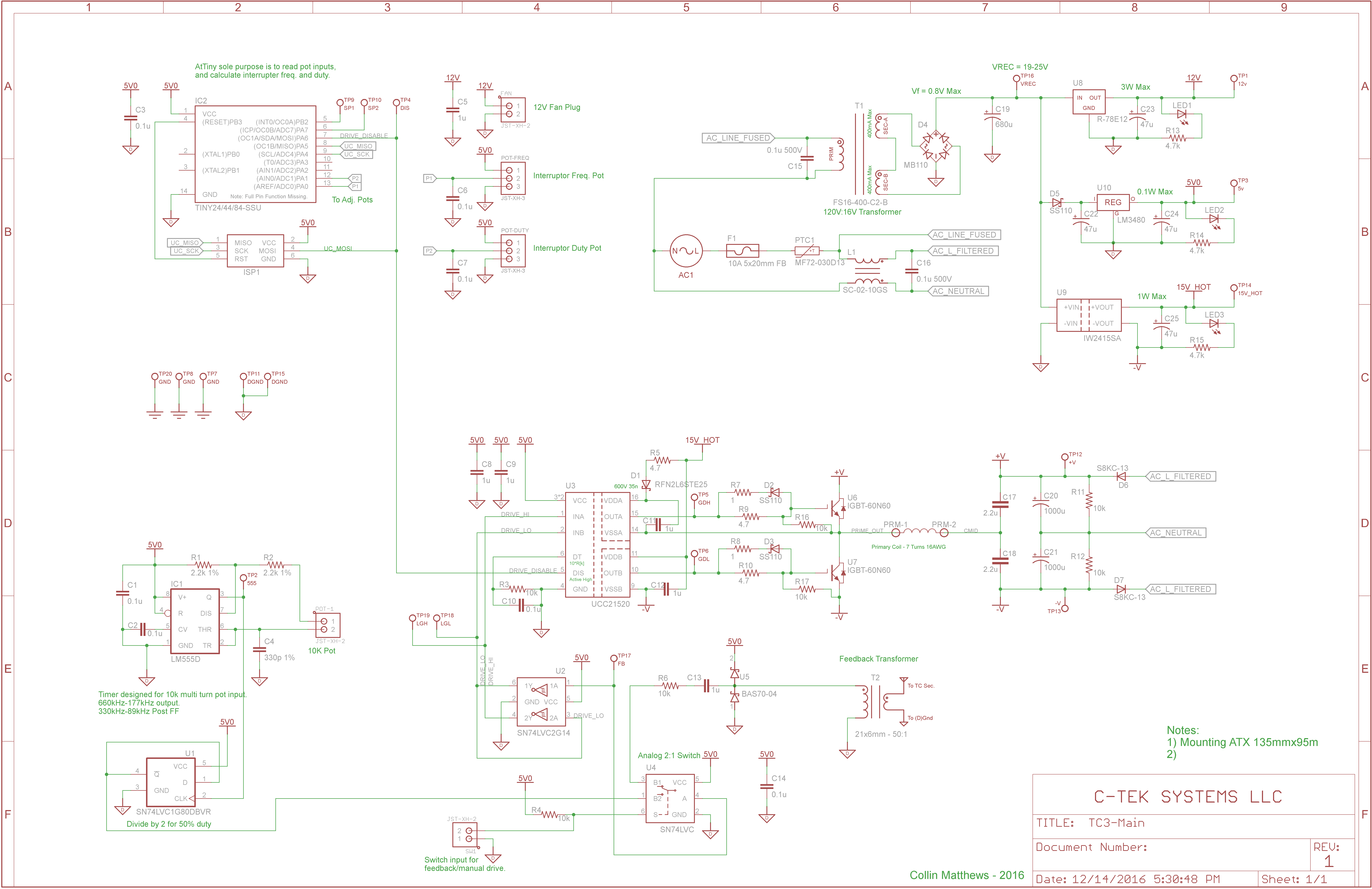
I know the schematic shows IGBTs, they were replaced by FETs (IPW50R280CE). enter image description here
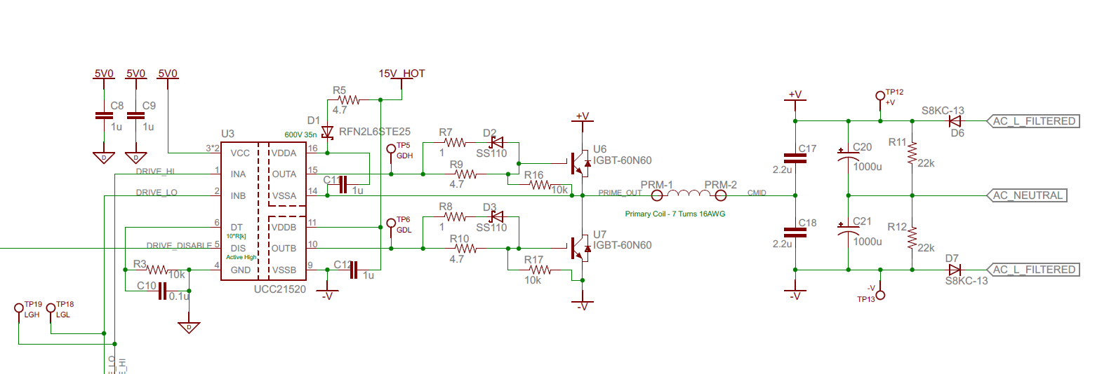
Also, the full schematic in case anyone is interested... enter image description here

\$\endgroup\$
9
  • \$\begingroup\$ What does the datasheet say about maximum allowable negative voltage? \$\endgroup\$
    – winny
    Commented Aug 6, 2017 at 17:01
  • \$\begingroup\$ @winny Ok valid point, it says -0.3V is max for drive pins. I didn't believe that a small ring would cause this when I have seen far worse with other designs. Maybe this chip is just very sensitive. So a larger gate resistance may help that. \$\endgroup\$
    – MadHatter
    Commented Aug 6, 2017 at 17:04
  • \$\begingroup\$ What's the part number on the FETs? \$\endgroup\$ Commented Aug 6, 2017 at 17:08
  • \$\begingroup\$ @ThreePhaseEel They are cheap IPW50R280CE. I want to make sure the driver works well before scaling up to $10 FETs. \$\endgroup\$
    – MadHatter
    Commented Aug 6, 2017 at 17:10
  • \$\begingroup\$ There you go! That's how I blew a tube of IR2113 when I did my master thesis. \$\endgroup\$
    – winny
    Commented Aug 6, 2017 at 17:26

1 Answer 1

1
\$\begingroup\$

As winny pointed out, the minimum voltage on the gate pin is -0.3V per the datasheet. My scope was showing an undershoot of ~1V for a brief time so I was violating the device specifications.

Upon changing the sinking resistor from 1 Ohm to 2 Ohms, and adding low capacitance Schottky diodes from source to gate, the undershoot disappeared and my gate driver operated successfully for over 30 minutes where previously it would die within 1 minute.

\$\endgroup\$

Your Answer

By clicking “Post Your Answer”, you agree to our terms of service and acknowledge you have read our privacy policy.

Not the answer you're looking for? Browse other questions tagged or ask your own question.