2
\$\begingroup\$

Prerequisites

I try to design a radio frequency low noise amplifier with a SiGe transistor (BFP740 infineon.) The amplifier is designed as a common emmiter with inductive degeneration.

Observation

  1. After I optimized for gain and NF I saw that first of all I had to choose a really small value for \$L_{ind., degen.}\$ to get reasonable amount of gain. As far as I understand it, it is possible to enhance the real impedance of the transistor amplifier but I cannot prove this statement.

  2. I could simply match the input to 50 ohm but as soon as I touch the output matching my input matching changes also.

Method

  1. MWO AWR plotted Gain(2,1) and NF(2,1) while tweaking L
  2. Matched input to 50 ohm while plotting Zin(1). Then matched output to 50 ohm while plotting Zin(2). After I saw my input changes also I added some elements and matched both to 50 Ohm

Questions

  1. What is the influence of L? I would be grateful about informations, explanations and formulas.
  2. What are reasons for the described phenomena? Is it because the capacitance between base and collector connects input to output (S12 is -23 dB).

Schematic of the design

Schematic of the LNA

\$\endgroup\$
3
  • \$\begingroup\$ Welcome! I think single-transistor RF LNA in common emitter configuration is reasonably clear, but I'm not quite sure where your inductor sits exactly. Would you mind adding a schematic to your question? \$\endgroup\$ Commented Oct 14, 2023 at 13:38
  • \$\begingroup\$ Hi Marcus! Thanks for the warm welcome. I added a schematic to clarify my design approach. According to Razavi: " Interestingly, the input impedance contains a frequency-independent real part given by gm*L1/CGS1. Thus, the third term can be chosen equal to 50 Ohm (page. 309). This I dont understand at all. \$\endgroup\$
    – mjg
    Commented Oct 15, 2023 at 9:31
  • \$\begingroup\$ There's the behavior that base input impedance is, in part, the rotation of emitter load impedance, so inductance rotates to resistance (or for stability purposes, capacitance rotates to negative resistance(!)), in the HF/cutoff region. Unfortunately I don't have the formulas or any references handy on this matter. \$\endgroup\$ Commented Oct 15, 2023 at 9:56

1 Answer 1

1
\$\begingroup\$

The answer to the problem:

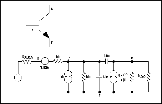
SiGe small signal model

You can clearly see that the capacitance between base and collector cannot be neglected (as I thought). In any case the input is coupled with the output.

I am still not sure if its possible to match both sides for 50 Ohm.

\$\endgroup\$

Your Answer

By clicking “Post Your Answer”, you agree to our terms of service and acknowledge you have read our privacy policy.

Not the answer you're looking for? Browse other questions tagged or ask your own question.