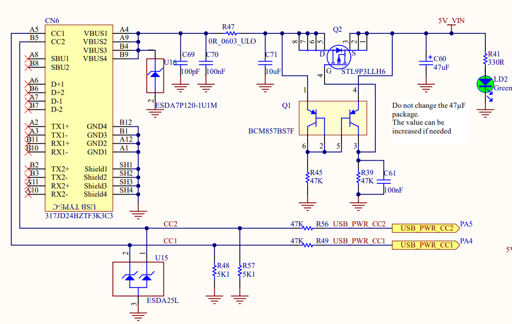
This is a schematic where USB-C is used to power a circuit device.
Notice that there are only VBUS and CC1 and CC2 (and of cource GND) connected to the USB-C holder.
Question:
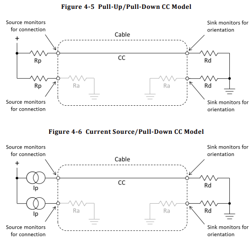
What is the use of CC1 and CC2 if your USB-C connector is only going to operate as a power source? Can I not connect them to GND or VBUS?
Update
The source of the schematic comes from STM32MP157D MPU and the direct link to the schematic.


