2
\$\begingroup\$

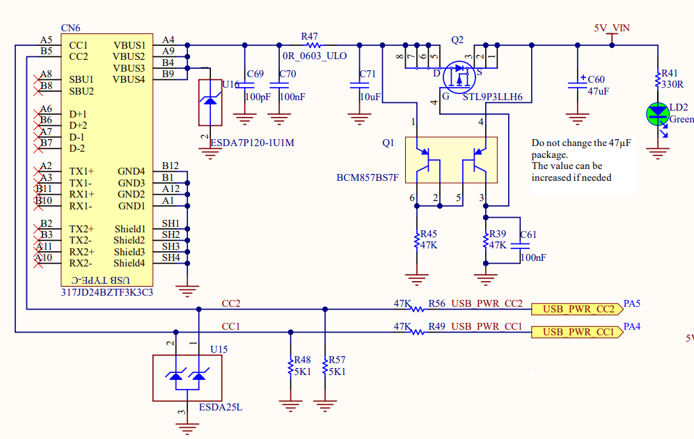
This is a schematic where USB-C is used to power a circuit device. Notice that there are only VBUS and CC1 and CC2 (and of cource GND) connected to the USB-C holder.

Question:

What is the use of CC1 and CC2 if your USB-C connector is only going to operate as a power source? Can I not connect them to GND or VBUS?

enter image description here

Update

The source of the schematic comes from STM32MP157D MPU and the direct link to the schematic.

\$\endgroup\$
0

3 Answers 3

6
\$\begingroup\$

The 5K1 pull-down resistors R48 and R57 shown connected to CC1 and CC2 respectively are the Rd terminations described in the Universal Serial Bus Type-C Cable and Connector Specification.

The Rd terminations are part of the Source-to-Sink Attach/Detach Detection in the USB Type-C specification. From section 2.3.1 Source-to-Sink Attach/Detach Detection:

Power is not applied to the USB Type-C host or hub receptacle (VBUS or VCONN) until the Source detects the presence of an attached device (Sink) port.

And are required to cause the Source to provide power to a USB Type-C power sink.


In response to the comment:

So is CC2 and CC1 going low or high? – euraad

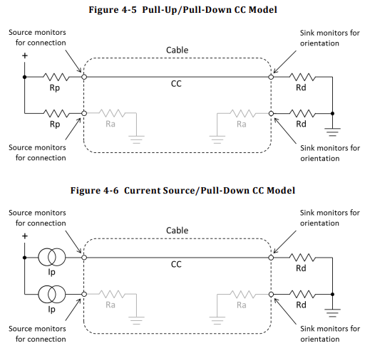
The specification listed above has the following in section 4.5.1.2.1 Detecting a Valid Source-to-Sink Connection:

enter image description here

Which means on the power sink:

  • One of CC1 or CC2 will be high.
  • The other CCx signal will be low.
  • Which CCx pin is high and which is low indicates the orientation of the USB Type-C cable.

The Ra resistors in the USB Type-C cable are specified as in the range 800 Ω to 1.2 kΩ.

\$\endgroup\$
11
  • 1
    \$\begingroup\$ So is CC2 and CC1 going low or high? \$\endgroup\$
    – euraad
    Commented Mar 24 at 15:44
  • 1
    \$\begingroup\$ @euraad I have tried to update the answer to address your comment. \$\endgroup\$ Commented Mar 24 at 15:57
  • 2
    \$\begingroup\$ @euraad Why confusing? How can two resistors be confusing? Surely the circuit you are powering is more complex than that? The idea with USB-C is that to prolong the life of the connector, no hot plugging happens. That is, when you make or break the connection, the supply current is off. That is accomplished by having the CC connection break first when unplugging, and make last when connecting. \$\endgroup\$ Commented Mar 24 at 17:22
  • 1
    \$\begingroup\$ @euraad You must be lucky enough to never have the experience of trying to figure out a compatible DC jack among a bunch of incompatible DC cables and connectors with millimeters differences, or trying to figure out what DC voltage is accepted by the device, or trying to figure out it's center-positive or center-negative, or trying to solder something onto a PCB but accidentally melting a piece of fragile plastic DC jack, or... Do you? The point of USB-C is a practical one, cables and standard and common with a reasonable metal plug. \$\endgroup\$ Commented Mar 25 at 12:28
  • 1
    \$\begingroup\$ @euraad Furthermore, if you only need to power a basic device from 5 V 500 mA from USB-C, you don't need to understand any of the implementation details involved. Simply attaching two 56 kΩ resistors on the CC pins, and you're done. Anything else is left as an exercise for the power supply makers. How is that confusing? This reason alone is my personal reason to use USB-C for random circuit prototype. No more "can't find cables" headaches. \$\endgroup\$ Commented Mar 25 at 12:49
1
\$\begingroup\$

USB specs forbid it.

The CC pins are used to detect if something is connected and negotiate what it is that is connected before power is applied or data communication is started.

You cannot have an USB Type-C receptacle with power supplied on it, because if you do, you will damage the devices if both have their supplies enabled and you connect them.

And since this is a device that is powered via USB-C, it must signal through CC pins that it is a device that requests power.

If this device uses USB-PD, then CC pins are used to transfer data packets to negotiate higher voltages and available current.

It seems that they go to analog inputs of a MCU which can measure the voltage on CC pins to know how much current is available without USB-PD.

\$\endgroup\$
0
\$\begingroup\$

CC1 and CC2 are required for communication with the charger (or other power source) in order to determine its current handling capability and/or negotiate higher power levels. You can't just draw as much current as you want from a USB connection without first asking whether that's okay. The CC lines also allow you to increase the output voltage of the charger if desired.

\$\endgroup\$

Your Answer

By clicking “Post Your Answer”, you agree to our terms of service and acknowledge you have read our privacy policy.

Not the answer you're looking for? Browse other questions tagged or ask your own question.