2
\$\begingroup\$

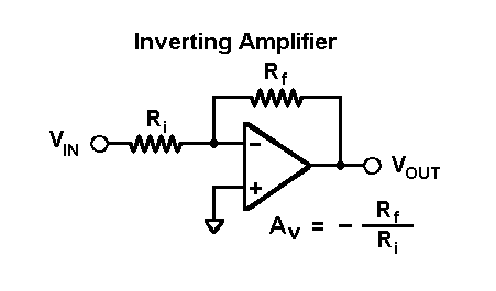
What I've learned so far from Navy school is that operational amplifiers are used as a substitute for transistor amplifiers and they contain three main circuits: the differential amplifier, common collector amplifier and the push-pull amplifier. They are represented by a triangle pointing to the right. My question is, why is the voltage gain \$-\frac{R_f}{R_i}\$

enter image description here

As far as I know, \$R_f\$ provides negative feedback to \$v_{in}\$, but why are we not treating \$R_{in}\$ and \$R_f\$ as part of a voltage divider like a non-inverting amplifier? I can see how they would reason that the incoming current is \$-\frac{v_{in}}{R_{in}}\$ without the voltage divider

\$\endgroup\$
5
  • 2
    \$\begingroup\$ One question per question please. \$\endgroup\$ Commented Nov 26, 2014 at 6:49
  • 1
    \$\begingroup\$ You can treat the resistors on the op-amp circuit as a voltage divider, but feedback keeps the divider output at GND. So the easiest way to relate Vin and Vout is to just observe that V- will be GND, and the current through the two resistors is the same. Vout/Rf = -Vin/Ri. So Vout/Vin = -Rf/Ri. \$\endgroup\$
    – user57037
    Commented Nov 26, 2014 at 7:27
  • \$\begingroup\$ I've deleted your second question, you can retrieve it from the review history. Please feel free to post it as a new question. \$\endgroup\$
    – clabacchio
    Commented Nov 26, 2014 at 8:06
  • 1
    \$\begingroup\$ Operational amplifiers are not a "substitute for transistor amplifiers". Fact: early operational amplifiers used tubes, including reasonably miniature ones that were produced as one modular package. Fact: modern (as of 1960-something) operational amplifiers are transistor amplifiers, packaged on a chip. An operational amplifier is an amplifier which implements mathematical operations like summing and integration. \$\endgroup\$
    – Kaz
    Commented Nov 26, 2014 at 22:36
  • \$\begingroup\$ Everything you ask about is explained very clearly in this video by Darryl Morrel \$\endgroup\$
    – Kamil
    Commented Nov 26, 2014 at 23:43

3 Answers 3

2
\$\begingroup\$

Of course, both resistors act as a voltage divider. However, you most consider the fact that you have TWO voltage sources at the same time (Vin and Vout). Hence, you must apply the superposition rule for calculating the voltage at the midpoint between both resistors:

\$V_{n1}=V_{in}\dfrac{R_f}{R_i+R_f}\$ and \$V_{n2}=V_{out}\dfrac{R_i}{R_i+R_f}\$ with \$V_n=V_{n1}+V_{n2}\$.

Now - because the opamp has a (very) high open-loop gain Aol (approaching infinity) you can set the differential voltage Vd=Vp-Vn between both input terminals to zero. As a consequence, we have \$V_n=V_{n1}+V_{n2}=0\$ which finally yields \$\dfrac{V_{out}}{V_{in}}=-\dfrac{RF}{Ri}\$.

\$\endgroup\$
0
0
\$\begingroup\$

If I understood your question well, in a voltage divider

schematic

simulate this circuit – Schematic created using CircuitLab

The output voltage Vout=Vin(R1/(R1+R2)). Thus the gain=1/(1+R2/R1)<1. But for your opamp, gain=-Rf/R1, thus gain>1, hence it is an amplifier unlike your voltage divider circuit, the reason why your Op-amp acts as an amplifier is because the inverting pin in this case acts as a ground with (ideally) infinite input resistance, which makes the voltage at that point zero but does not let the current sink. This is the speciality of operational amplifiers, all other ordinary voltage sources have (ideally) zero impedance, hence if your voltage sinks at a point, so does your current, but op-amps have defined a way to sink voltage without sinking your current, hence when an op-amp is used as an operator to different circuits (in this case voltage divider circuit), you outputs which you wouldn't be getting in that circuit, had you not used an op-amp.

For your second circuit, the output across the bridge is a rectified sine wave, loading it with C1 smooths the sine wave, so C1 acts like a smoother circuit in itself, after which LM7805 acts as a voltage regulator and outputs a, if I remember well, smooth 5V non-pulsating DC as the output. So, basically it's a rectification circuit with smoothing applied.

\$\endgroup\$
4
  • \$\begingroup\$ This is all pretty confused. All you're trying to say is that the op amp has infinite input impedance. This is only greater than other circuits, not a unique peculiarity of op amps. \$\endgroup\$
    – user207421
    Commented Nov 26, 2014 at 21:37
  • \$\begingroup\$ yes the ideal op-amp DOES have infinite input impedance, at least when you are trying to understand op-amp circuits that are designed well within its operational range like the inverting gain amplifier, you make the assumption to be infinite, that is exactly why it grounds your signal without sinking your current, the inverting terminal is used for applications where you need a voltage source with very high impedance, this is exactly what makes it such a popular tool when applying feedback, otherwise it is just a differential amplifier with a very high gain. \$\endgroup\$
    – Ghosal_C
    Commented Nov 26, 2014 at 21:54
  • \$\begingroup\$ ubuntu_noob: What I am surprised about is the following: You have mentioned the term "negative feedback" not at all. Don`t you think that feedback is the only explanation for the fact that the inverting terminal "acts as a ground"? \$\endgroup\$
    – LvW
    Commented Nov 27, 2014 at 8:36
  • \$\begingroup\$ @LvW: Yeah I should have, what I wanted him to understand was that it sources/sinks voltage without sourcing/sinking the current, that's the important point whenever there is -ve feedback... \$\endgroup\$
    – Ghosal_C
    Commented Nov 30, 2014 at 23:49
0
\$\begingroup\$

In the beginning, arguably the three most important things to remember about an ideal opamp operated without feedback is that it exhibits infinite input-to-output gain, that if the voltage on its non-inverting (+) input goes more positive than the voltage on its non-inverting (-) input, its output will be forced to as close to the positive rail as it can be, and that if the voltage on its non-inverting input goes less positive than the voltage on its inverting input, its output will be forced to as close to the negative rail as it can be.

Operated using feedback and implicit in the operation of the opamp - but perhaps not immediately obvious from the foregoing - is the fact that the opamp's output will do whatever it has to to make the voltages on the opamp's inverting and non-inverting inputs equal.

THE NON-INVERTING VOLTAGE FOLLOWER:

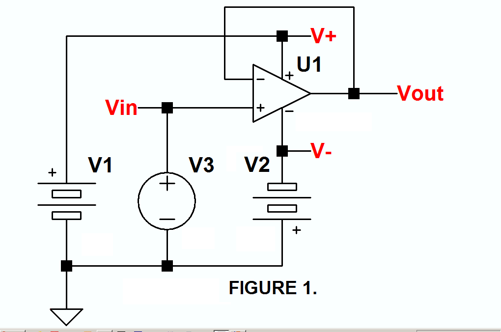
Referring to Figure 1, following, U1 is wired as a non-inverting follower with, say, zero volts on Vin, which is the non-inverting (+) input of U1.

In operation, then, if Vin (U1+) at zero volts was more positive than U1-, Vout would go more positive and, being connected to U1-, would force U1- closer and closer to the positive rail until Vin, Vout, and U1- were all equal to zero volts.

If the opposite were true and Vin at zero volts was less positive than Vout, then Vout (and U1-) would be forced closer and closer to the negative rail until the voltages on Vin, Vout,and U1- were all equal to zero volts.

Notice that - in any case - Vout will be forced to servo toward the voltage on U1+, whatever that voltage may be, which is why this circuit configuration is called a "voltage follower" and always has a gain of 1.
enter image description here

THE NON-INVERTING AMPLIFIER:

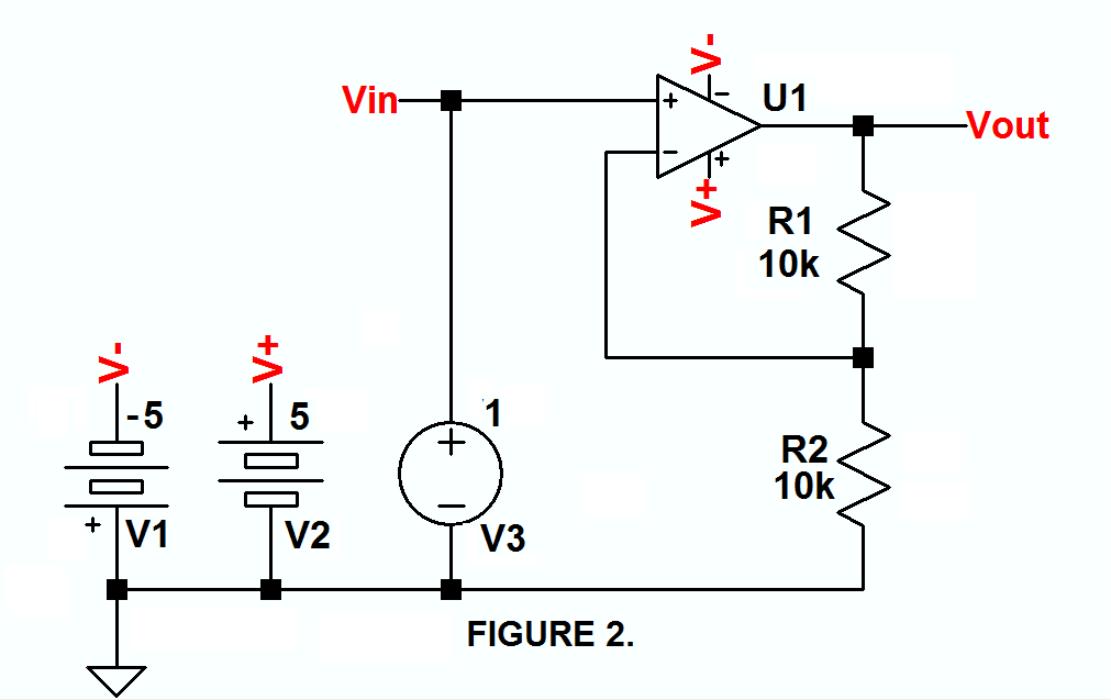
Referring to Figure 2, below, U1 is wired as a non-inverting amplifier with one volt on Vin, which is the non-inverting (+) input of U1. The gain of the circuit is dependent on the ratio of the resistors in the voltage divider R1 R2, and is equal to:

$$\ Av= 1+\frac{R1}{R2} $$

In operation and - as noted earlier - since the goal of the opamps's output is to do whatever's necessary to make the voltage on U1- equal to the voltage on U1+ and, since the voltage divider is functioning as an attenuator, U1's output amplitude must be equal to the voltage appearing on U1+ times the ratio of R1 to R2 to make that happen.
enter image description here

THE INVERTING AMPLIFIER

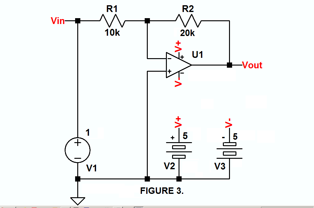
Finally referring to your question: "Why is the voltage gain \$ -\frac{Rf}{Ri}\$ " and to Figure 3, below, U1 is wired as an inverting amplifier with one volt on Vin, which is connected through R1 to the inverting (-) input of U1. The gain of the circuit is dependent on the ratio of the resistors in the voltage divider R1 R2, and is equal to:

$$\ Av= - \frac{R2}{R1} $$

In operation, with Vin being positive and U1+ being connected to zero volts, Vout must go negative in order to make the voltage on U1- equal to the voltage on U1+ and, consequently, Vout is an inverted version of Vin.
enter image description here

\$\endgroup\$

Your Answer

By clicking “Post Your Answer”, you agree to our terms of service and acknowledge you have read our privacy policy.

Not the answer you're looking for? Browse other questions tagged or ask your own question.