0
\$\begingroup\$

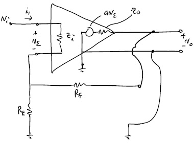
For a standard non-inverting amplifier as below:

enter image description here

With nodal analysis, I got $$\frac {v_o} {v_i}=\frac {R_EZ_o+aZ_iR_E+aZ_iR_f} {R_ER_f + R_EZ_i + R_EZ_o + R_fZ_i + Z_iZ_o + R_EaZ_i}$$

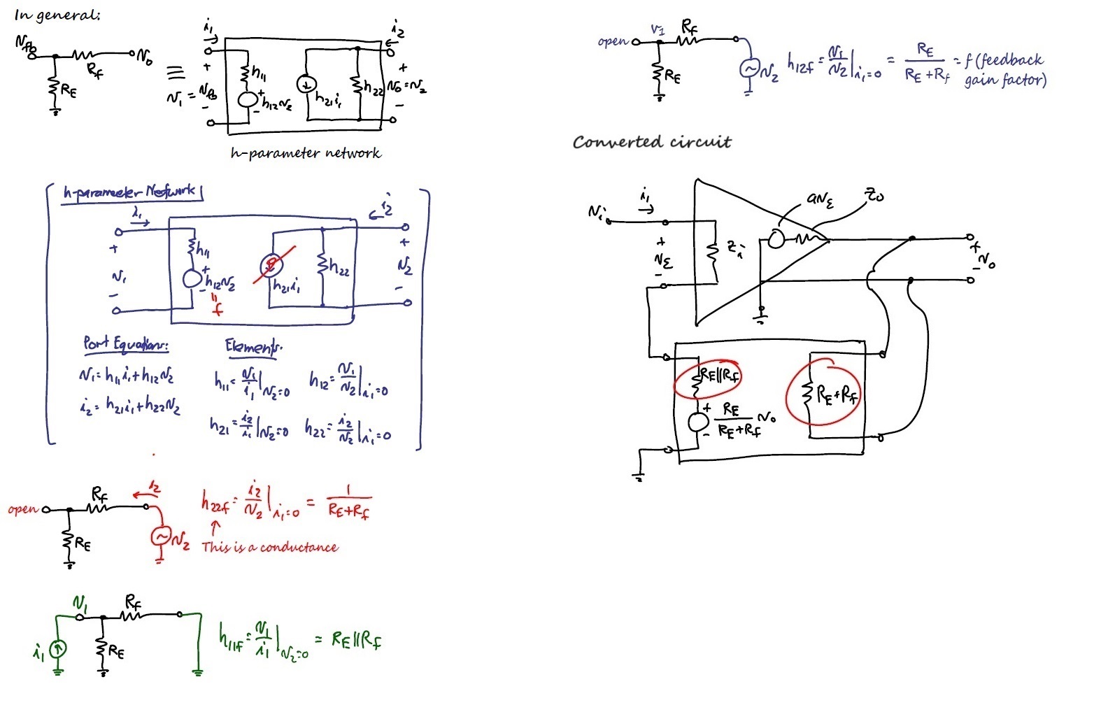
However, with the feedback network of the amplifier converted to a h-parameter network as below:

enter image description here

With nodal analysis on this converted circuit, I got $$\frac {v_o} {v_i}\\=\frac {aZ_i(R_E + R_f)^2} {R_ER_f^2 + R_E^2R_f + R_E^2Z_i + R_f^2Z_i + 2R_ER_fZ_i + R_ER_fZ_o + R_EZ_iZ_o + R_fZ_iZ_o + R_E^2aZ_i + R_ER_faZ_i}$$

I checked with Matlab to make sure the two results are different. My question is, are they suppose to produce different results? If so, why are they different? My prof is showing this so I expected they should be equivalent and produce same results.

\$\endgroup\$

2 Answers 2

0
\$\begingroup\$

The h parameter business appears to be an attempt to thrust the op amp circuit into a form where block diagrams can be identified corresponding to feedback network, summer, etc. However unlike many control systems it is not possible to break the feedback loop without taking care that input resistances, etc. are preserved. To put it bluntly, I find this sort of thing convoluted and baroque. On the other hand node equations are easy to get right and must give the right answer.

I would use the result from the node voltage equations to troubleshoot the h parameter approach. Personally I wouldn't use this approach in an op amp circuit.

By the way we know the right answer for Zi going to infinity and Zo to zero. That may allow you to rule out one of the answers. And indeed, only one is correct.

\$\endgroup\$
0
\$\begingroup\$

Ok, they match if I do not eliminate $$h_{21}$$ in the model.

\$\endgroup\$

Your Answer

By clicking “Post Your Answer”, you agree to our terms of service and acknowledge you have read our privacy policy.

Not the answer you're looking for? Browse other questions tagged or ask your own question.