10
\$\begingroup\$

According to all textbooks and articles, a thermocouple must have a cold junction somewhere on the middle of it.

enter image description here

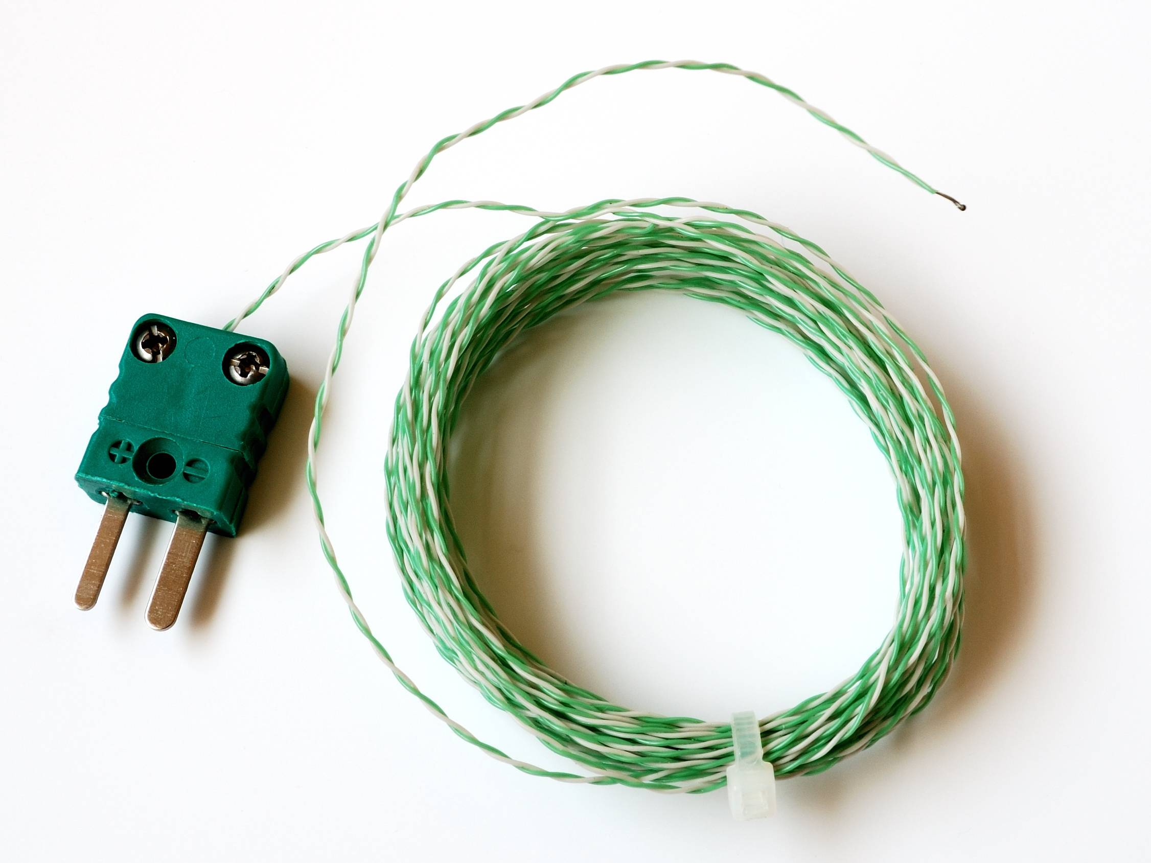
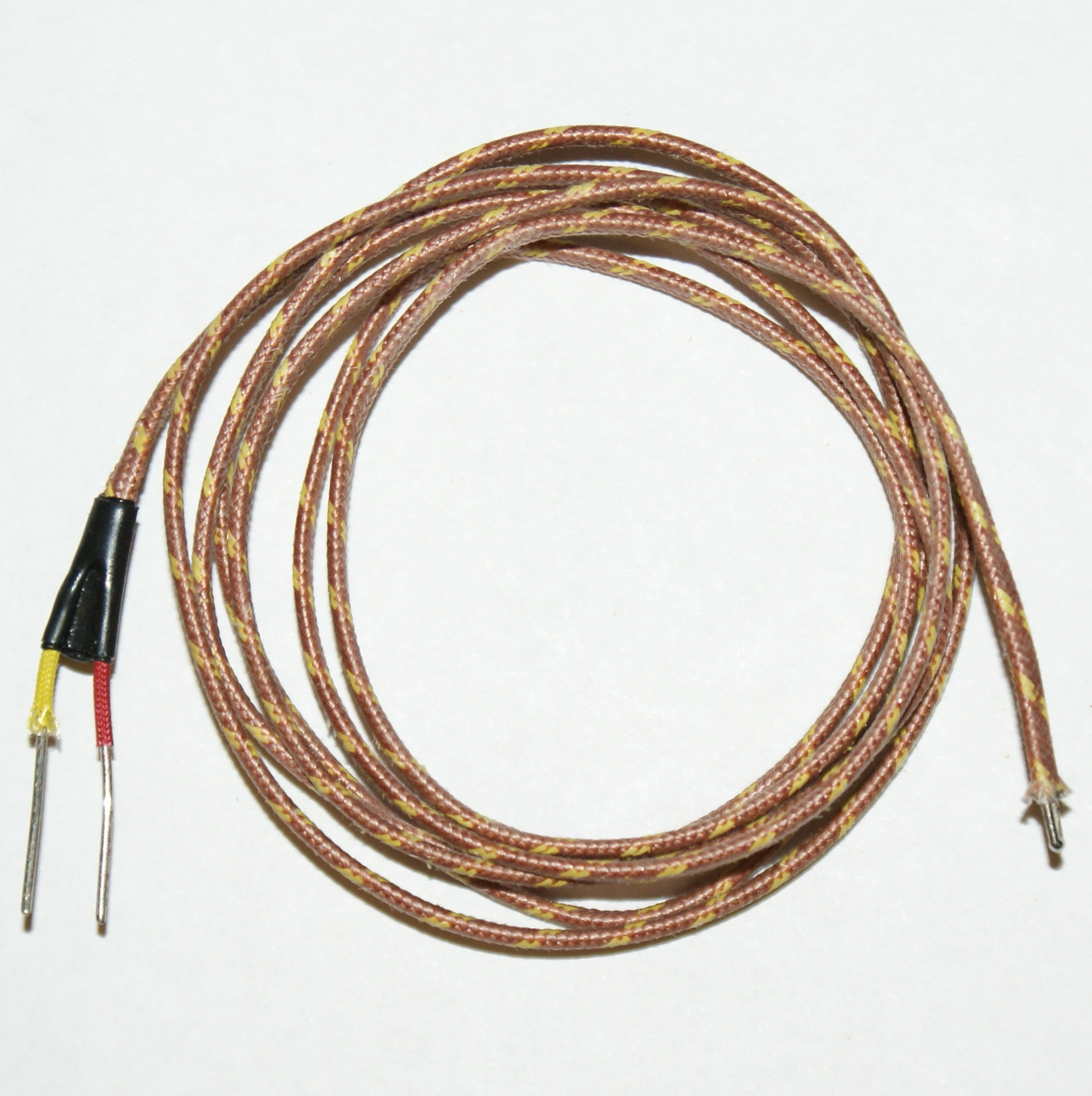
But none of the commercial products have a middle point or a marked spot for indicating the position of the cold junction. They are simply nothing but a long wire.

enter image description here enter image description here

I want to place another temperature sensor near the cold junction and subtract its temperature from the measured hot junction temperature for more precise measurement. So, I need to know the location of the cold junction. How do I find it?

\$\endgroup\$
1
  • \$\begingroup\$ You provide it. \$\endgroup\$
    – PlasmaHH
    Commented Mar 24, 2015 at 12:45

5 Answers 5

12
\$\begingroup\$

Your cold junctions (at least two!) are where you connect the two (different!) thermocouple metals to your circuit. Note that this can be in multiple steps, like: thermocoupe - connector - wires - PCB. These are all cold junctions. Keep them all at the same temperature and measure that temperature. If no heating or chilling effects occur that is simply the ambient temperature, and you can use a temperature sensor anywhere on your PCB, but it won't hurt to place it near the thermocouple connector and put heat-producing components as far away as possible.

\$\endgroup\$
6
\$\begingroup\$

These days, there are often (if not usually), virtual cold junctions in amplifiers meant to deal with thermocouples. It is often referred to something like "electronic ice point reference". The temperature of the virtual cold junction is measured by some other means, and the temperature is internally compensated for.

\$\endgroup\$
2
4
\$\begingroup\$

For the Thermocoupler with the connector attached, the cold junction is inside the connector

There the 2 metals are connected to the pins of the connector, so here you'll have the cold junction.

For the thermocoupler with the blank wires the junction is either made by you, when you connect the two wires, or it is inside the black part just above.

\$\endgroup\$
1
  • 2
    \$\begingroup\$ This is often not the case. Many of the connectors have conductive parts made from the thermocouple alloys, and are thus specific to a certain type of thermocouple. \$\endgroup\$ Commented Mar 24, 2015 at 14:25
3
\$\begingroup\$

The 'cold' junction (actually it can be warmer than the measuring junction), is where the thermocouple material wires transition to the circuit material (usually copper). For most thermocouples (other than type T copper-Constantan) there are two junctions that will be physically close together, typically at a screw terminal strip.

If you want any kind of accuracy you must prevent thermal gradients in the region of that terminal strip (prevent air from blowing on it, for example), minimize heating from other parts of the circuit, minimize disturbances brought in through the thermal conductivity of the wires themselves, and use a sensor to measure accurately the temperature of the point where the wires transition to copper. Keeping the thermal mass large in the region of the terminal block helps. A 3°C error between your measured temperature and the temperature of those junctions means you will have (typically) extra ~3°C error in your measured temperature, so the cold junction compensation measurement accuracy is extremely important if high accuracy and/or temperatures close to ambient are being measured. If it's a high temperature you're measuring (say 400°C) and you don't care about 5°C you can be a lot more sloppy. For at least one thermocouple (B) the cold junction is almost not required because of the extreme non-linearity (it actually reverses below room temperature so it is not monotonic).

The traditional method controlled the temperature at the transitions with an ice bath, but that's clearly impractical for most modern applications.

Once you have the temperature you can calculate the resulting thermoelectric voltage from the cold-junctions, adjust the measured EMF by that factor, and calculate the temperature from the adjusted EMF. A straight linear correction can be used (so many uV/°C) if sloppy accuracy is acceptable, but in general both forward and reverse functions are slightly nonlinear, so it's a compromise.

\$\endgroup\$
5
  • \$\begingroup\$ My wife's kiln has a thermocouple-based thermometer that uses a meter movement with no powered electronics; would such a thing likely just "assume" that the cold junction is sitting at a reasonable room temperature (e.g. 77F), or are there good passive approaches to ambient temperature compensation? \$\endgroup\$
    – supercat
    Commented Mar 24, 2015 at 15:32
  • 1
    \$\begingroup\$ @supercat Usually those pyrometers (good industrial ones anyway) use a bimetal strip that deflects the meter to follow room temperature (linear correction), but possibly consumer grade ones are just microammeters that you would adjust with that prominent zero screw to read nominal room temperature. At 1000°C 10 or 20 degrees doesn't make much difference on a 1%-2% accurate meter anyhow. They also assume a certain source resistance such as 10\$\Omega\$ (may be marked on the meter)- another potential error source. \$\endgroup\$ Commented Mar 24, 2015 at 15:47
  • \$\begingroup\$ I hadn't thought of embedding a bimetal strip in the meter itself; that would seem like a good way to improve accuracy. When annealing glass, temperatures don't have to be super-precise, but something that adds a 20-degree margin of error would noticeably reduce the margin of error one could accept from other causes, so I would guess that it may be cheaper to use a bimetal strip and be able to accept looser tolerances elsewhere than refrain from using one and reduce the error budget for other components. \$\endgroup\$
    – supercat
    Commented Mar 24, 2015 at 15:54
  • \$\begingroup\$ @supercat AFAIUI, glass is a bit more sensitive to the temperature than ceramic firing. \$\endgroup\$ Commented Mar 24, 2015 at 16:12
  • \$\begingroup\$ My wife's kiln is rather low and flat, and has doors on the front and top, so I think it's designed for use either annealing glass beads (load from the front when hot) or fusing glass (load from the top when cold). Annealing is typically done at about 1000F. Too much hotter and the glass may slump; too much cooler and beads may cool with latent stresses. \$\endgroup\$
    – supercat
    Commented Mar 24, 2015 at 16:26
1
\$\begingroup\$

The "cold junction" for a thermocouple, is any "reasonable" distance from the tip of the thermocouple. The reason for the distance ambiguity, is that it depends on the thermal insulating properties of the material between the thermocouple and the "cold" junction. If you have good thermal insulation, a few inches will suffice. If not, it may need a few feet and an "ice bath." If air surrounds the "cold junction", then its temperature will be ambient, otherwise it will be the temperature of the "bath" used to cool the junction.
No compensation will be required, if you calibrate the uAmeter, using accurate reference points (ice water, 0 oC; ambient temp 25 oC; boiling water, 100 oC; etc.).

\$\endgroup\$

Your Answer

By clicking “Post Your Answer”, you agree to our terms of service and acknowledge you have read our privacy policy.

Not the answer you're looking for? Browse other questions tagged or ask your own question.