6
\$\begingroup\$

For the most part, all solderless breadboards are alike. 5 or 6 contacts spaced 0.1" connected across, a gap (typically 0.3" wide), and 5 or 6 contacts more, and repeated x times down the other length (0.1" from each other). Some have rails on either end that are connected most of the way through.

enter image description here

My question is, does a breadboard without the center gap exist? I know there are ones with a wider gap (0.6"), but I have not found any without the gap. Do they have a different name?

My goal is simply being able to plug in a standard Dual In Line header without needing an adaptor, or modifying the breadboard (cutting out the middle, or cutting a contact set in half)

\$\endgroup\$
2
  • 1
    \$\begingroup\$ Is photoshop an option? ;o) \$\endgroup\$
    – jippie
    Commented Dec 3, 2013 at 21:26
  • \$\begingroup\$ @jippie only if you use Photoshop 1.0 on a classic Mac. \$\endgroup\$
    – Passerby
    Commented Dec 4, 2013 at 5:23

4 Answers 4

5
\$\begingroup\$

Idea: Get some stripboard, and solder rows of 0.1" spaced female headers to it to create a facsimile of a breadboard.

You can cut across traces to disconnect adjacent headers from each other that are spaced only 0.1" apart, thereby creating the receptacle you want.

\$\endgroup\$
5
\$\begingroup\$

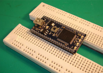
You may want to consider an adaptation of the idea shown here.
enter image description here

The idea is to split the board down the middle. (A better choice of board is the type that has an open slot down the middle with the sides connected across only in a few places). As seen above the board was split to allow it to efficiently support a wide device without covering up all the adjacent holes.

The modified idea would be to use some sandpaper laid grit side up on a nice flat surface. Then sand the inner edges of the separated board so that they become thin enough that when the two sides are slid next to each other that the rows of holes get close to the 0.1" spacing that you need for a standard dual row header. While sanding use care to hold the pieces upright in a square manner and apply even pressure so that the whole length gets sanded down in an even manner. Sometimes it can be useful to swap the piece end for end several times during the sanding process to even out the variation of pressure on how you hold the part against the sand paper.

You may find that to get the parts sanded enough to achieve the 0.1" spacing that the ends of the metal contact strips may become exposed. If this happens you can over-sand the part by the thickness of piece of plastic electrical tape and then run a strip down the middle to insulate the exposed metal from one side to the other.

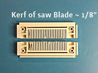
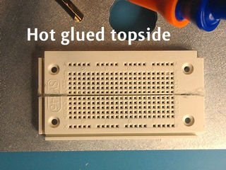
That can be seen in this Instructable, requiring careful cutting (after removing the contacts), insulation, and gluing it back together, a 0.1" spacing is possible.
enter image description hereenter image description here

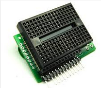
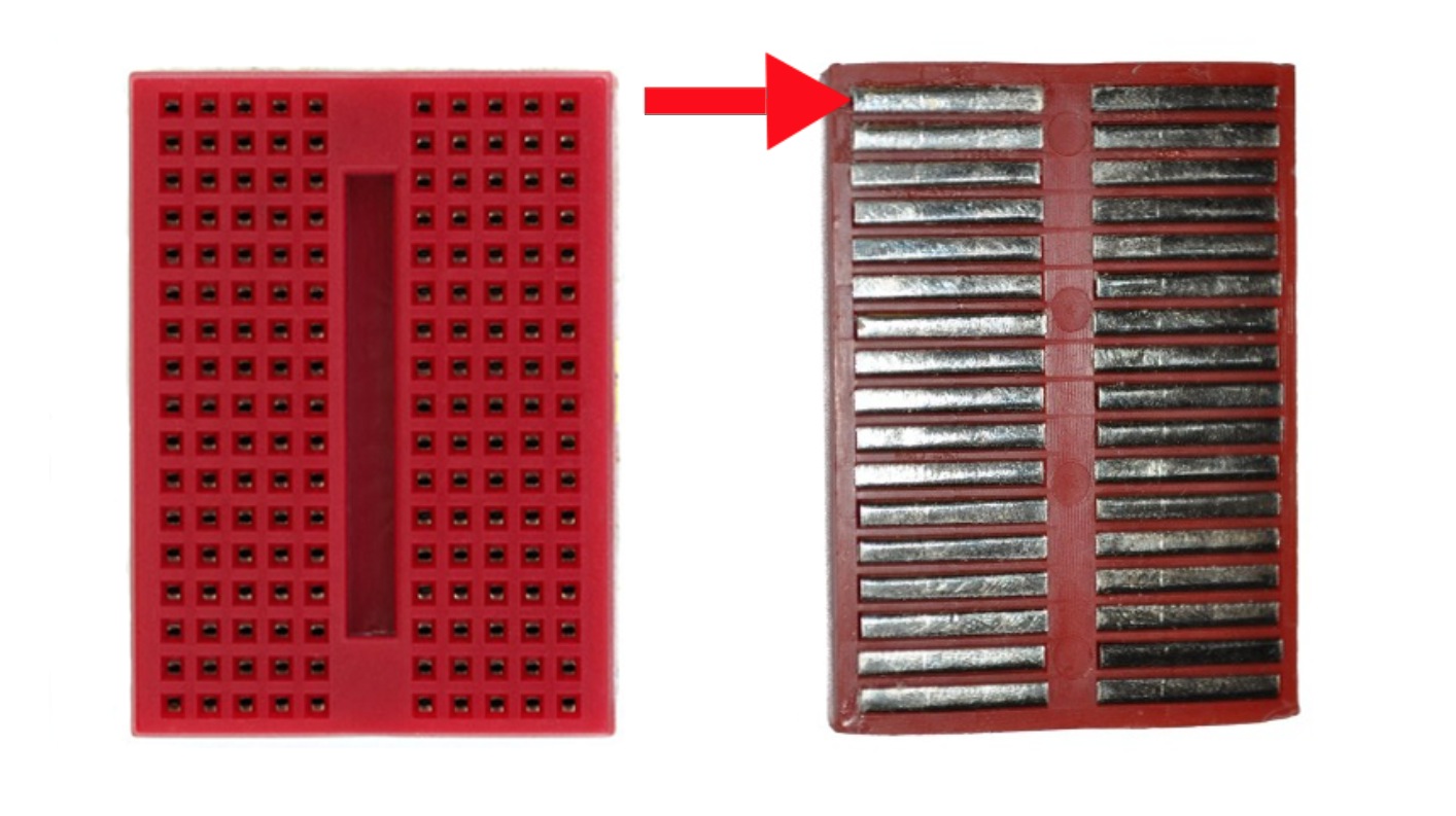
Here is an example of a solderless breadboard that has an open slot down the middle such that there is far less plastic to remove.
enter image description here

\$\endgroup\$
3
  • \$\begingroup\$ Yea, I know that cutting is an option (not that I have seen any with an empty hole/channel down the middle), I just wanted to avoid that, for the obvious reason being that 0.05" margin on each end might be a bit too razor thin to do by hand without a table router (and sanding gets messy and/or hot melting plastic flaking everywhere) \$\endgroup\$
    – Passerby
    Commented Dec 4, 2013 at 5:56
  • \$\begingroup\$ @Passerby - The sanding would not cause hot and melting plastic if you do it by hand. (I do this type of thing all the time). It can be a bit dusty and thus the reason to do it in a garage!! I would NOT try working the cutting of the proto board with a table router. As far as a proto board with a slot down the middle I've shown an example in my posting. \$\endgroup\$ Commented Dec 4, 2013 at 6:06
  • \$\begingroup\$ Ah I thought you meant completely open hole, not just a gap. \$\endgroup\$
    – Passerby
    Commented Dec 4, 2013 at 6:57
1
\$\begingroup\$

I may have seen a few breadboards that lack the center gap but they are VERY small boards, probably not suitable for what you are doing. For the most part all of them have a gap to allow for chips to be plugged in.

\$\endgroup\$
1
  • \$\begingroup\$ The lego looking 25 tie-point ones? Or the single shared column ones with solder tails (2x4, 3x5, 2x8) ones? \$\endgroup\$
    – Passerby
    Commented Dec 4, 2013 at 5:51
1
\$\begingroup\$

Hackaday noted two workarounds in their August 2015 article Literal breadboard hack forces it to accept dual pin headers:

  1. Disassemble the breadboard, remove the relevant conductive tracks, cut them in the appropriate place, and then put them back in.

  2. Add a long-legged header and some judicious pin-bending to extend one row of legs far enough that it can sit on the far side of the gap that runs along the middle of an ordinary solderless breadboard.

However, these workarounds are both fiddly and time-consuming. I wish manufacturers would make solderless breadboards that can accommodate 2-row 2.54mm pin headers without short-circuiting them, so that people could use such headers to prototype easily, without needing to engage in time-consuming and fiddly workarounds.

Edit: I've just learned that Adafruit makes "IDC Breakout Helper" headers that enable 2-row pin headers to be conveniently used with ordinary solderless breadboards. Hopefully this will become a standard item for electronics manufacturers to make!

\$\endgroup\$
3
  • 1
    \$\begingroup\$ That item is essentially a Bottom Entry or Pass Through entry header. It's commonly stocked by manufacturers and distributors like Digikey, just not used often by hobbyists. \$\endgroup\$
    – Passerby
    Commented Dec 5, 2015 at 5:55
  • \$\begingroup\$ I've used the Adafruit "IDC Breakout Helper". Careful of the length of the pins; they are sufficiently short that some breadboards don't hold them well. \$\endgroup\$ Commented Dec 5, 2015 at 6:48
  • \$\begingroup\$ @Passerby, thanks for that; great to know the generic term for these parts, and that they are more widely available. James: noted, thanks! \$\endgroup\$
    – user2023
    Commented Dec 6, 2015 at 1:02

Your Answer

By clicking “Post Your Answer”, you agree to our terms of service and acknowledge you have read our privacy policy.

Not the answer you're looking for? Browse other questions tagged or ask your own question.