1
\$\begingroup\$

Why do we call some amplifiers this way? I mean lets say one call an amplifier as: "Current in voltage-out amplifier". I dont understand this because if current is in then inevitably voltage is also in.

What makes us naming the type of input here(current or voltage)?

For example is common-emitter BJT NPN amplifier voltage in voltage out? But some current is also in and some current is also out. Why choose one?

What is an example of current in voltage out amplifier? And if current is in then some voltage also must be in why we call it current in?

EDIT: Please if possible give examples with single BJT transistor amplifiers. Because that creates my current confusion.

\$\endgroup\$
4
  • \$\begingroup\$ Why do we call some amplifiers this name? or Why does this BJT setup entail this type of amplifier? If the former, then in principal it shouldn't matter whether you use a BJT or an Op-Amp to explain this concept \$\endgroup\$
    – Iancovici
    Commented Jan 22, 2016 at 12:24
  • \$\begingroup\$ in bjt ce a little current is in which controls Ic but voltage is also in between base and emitter. so which one is in? \$\endgroup\$
    – user16307
    Commented Jan 22, 2016 at 12:27
  • \$\begingroup\$ The question if the BJT is a current or voltage controlled device was INTENSIVELY and CONTROVERSELY discussed elesewhere! \$\endgroup\$
    – LvW
    Commented Jan 22, 2016 at 12:36
  • \$\begingroup\$ "transimpedance amplifier" is a common term for them. \$\endgroup\$
    – user16324
    Commented Jan 22, 2016 at 13:02

4 Answers 4

5
\$\begingroup\$

What is an example of current in voltage out amplifier? And if current is in then some voltage also must be in why we call it current in?

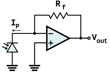
A transimpedance amplifier (TIA) is "current in" and "voltage out" circuit. The input impedance is theoretically zero ohms so if you tried to put a milli-volt at the input the current taken (theoretically) would be infinite.

They are quite commonly used for amplifying photodiodes: -
enter image description here

Reason: the output from a photodiode (PD) is current for a given light-power-density on the device. It produces a current out and, if you connected the PD output to a resistor, it would still try to push the same current through that resistor for the same light input. The side effect of this is that there will be a voltage produced across that resistor to keep ohms law happy.

So why not just feed the PD output to a resistor and use a voltage amplifier? You can do this but what you will find is that if the light is modulated (i.e. a typical data transmission from say a fiber optic), the presense of the resistor (and the self-capacitance of the PD) will form a low pass filter and make the data look very non-ideal.

So a TIA is used because its input impedance is zero ohms i.e. it is a current-in device with zero volts produced. With zero volts produced at the input, the self-capacitance of the PD is defeated and you can get significantly higher bandwidths thru the amplifier.

For example is common-emitter BJT NPN amplifier voltage in voltage out? But some current is also in and some current is also out. Why choose one?

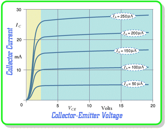
Strictly speaking (with respect to the physics) a BJT is a voltage-input device and any current taken into the base is all part and parcel of the Shockley diode equation. Regarding the output, it is generally accepted that it is a current-out device because of this: -
enter image description here

For a given base voltage (that gives rise to a given base current), the collector current is largely constant (flat) for a vast change is colelctor-emitter voltage. This is normally where a linear amplifier uses a BJTs characteristic i.e. it's a current out device BUT that current out converts to a voltage out for a given collector resistance.


The Schockley equation for a diode tells you what current flows in the diode but a variant of this is the ebers-moll equation. This tells you the collector current for a given Vbe: -
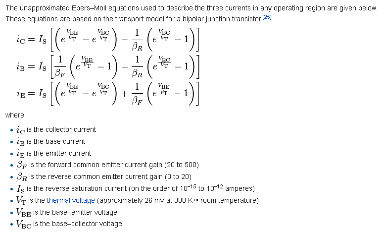
enter image description here

The important thing to note is that the BJT is a voltage-in device and a current-out device. Look at the top equation - what drives collector current is Vbe and Vbc BUT Vbc is negative (collector and base reverse biased) so the dominant part of the equation is governed by Vbe and not Ib - base current is a by-product that is convenient to use because base current (as a side-effect) and collector current conveniently appear to be proportional to each other. As far as I know (and I'm no physics expert), this happy accident is just that and has "convenienced" the use of hFE as a measure of Iout/Iin.

\$\endgroup\$
24
  • \$\begingroup\$ is there a transistor equivalent of this? Let me expound on my confusion here. Consider a BJT common emitter amplifier. What if I know both input current and voltage? Will it be voltage in or current in??? \$\endgroup\$
    – user16307
    Commented Jan 22, 2016 at 11:59
  • \$\begingroup\$ A BJT (getting down to the nitty gritty in the physics) is ultimately a voltage input device but current also flows because of the base-emitter region is a forward biased diode. An op-amp is a bunch of BJTs with negative feedback (Rf) so, in a way there kind of is a BJT equivalent. \$\endgroup\$
    – Andy aka
    Commented Jan 22, 2016 at 12:01
  • \$\begingroup\$ do you mean this terminology makes sense with opamps rather than transistor amplifiers? \$\endgroup\$
    – user16307
    Commented Jan 22, 2016 at 12:04
  • 1
    \$\begingroup\$ SPICE is a very versatile tool to demonstrate that a designed circuit works as desired, but it should not be used for designiung the circuit. This would be nothing else than a trial-and-error game with questionable results. \$\endgroup\$
    – LvW
    Commented Jan 22, 2016 at 13:37
  • 1
    \$\begingroup\$ @Andy aka-ohh no, it was my reply to user`s16307 question "do you use them when designing transistor circuits"? You can trust me, I am aware of your technical competence. Sorry, I forgot to write down to whom it was concerning (linguistic OK?). \$\endgroup\$
    – LvW
    Commented Jan 22, 2016 at 14:07
3
\$\begingroup\$

Current and voltage are related by the impedance of whatever they are applied to. You can only chose two of voltage, current, and impedance. Put another way, there are only two degrees of freedom between these three parameters.

Suppose a amplifier had 0 input impedance, and the parameter it measured to amplify was the current. The voltage would always be 0.

In fact, it is possible to do this:

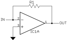
Assuming ideal parts, consider what happens when a current is dumped onto IN. That makes the - input higher than the + input, so the opamp output goes down. Eventually it goes down enough so that the current thru R1 matches the current being dumped onto IN. In fact, the current onto IN always goes thru R1, producing a voltage across it. Due to how the feedback around the opamp works, the - input is always held at the same voltage as the + input.

This circuit is a amplifier with current input and voltage output. Such a thing has the special name of transimpedance amplifier. Note that its gain is not dimensionless. The gain is the output voltage divided by the input current. Voltage divided by current has units of resistance. This makes sense since one way to look at a resistor is as a voltage to current converter.

In the above circuit, this transimpedance amplifier has a gain of -R1. If R1 is 3.3 kΩ, for example, and you put 1 mA in, then the output will be (1 mA)(-3.3 kΩ) = -3.3 V.

\$\endgroup\$
7
  • \$\begingroup\$ This is a great example of a TIA, but the o.p. doesn't understand the difference between "current-mode" and "voltage-mode" operation. \$\endgroup\$
    – rdtsc
    Commented Jan 22, 2016 at 12:10
  • \$\begingroup\$ im not asking about opamps. please see my edit \$\endgroup\$
    – user16307
    Commented Jan 22, 2016 at 12:16
  • \$\begingroup\$ @user: You asked about current-in voltage-out amplifiers. I used a opamp circuit to illustrate the concept and show that these things are actually possible to useful approximations. \$\endgroup\$ Commented Jan 22, 2016 at 12:20
  • \$\begingroup\$ yes great answer indeed but if you read my question im writing about CE single transistor amplifier before the edit. thanks \$\endgroup\$
    – user16307
    Commented Jan 22, 2016 at 12:22
  • 1
    \$\begingroup\$ user16307: OK, I see your point. But a general answer is not possible, because we have to define: What is the "stage" we are referring to? The BJT is regarded as a current source - however, the collector resistor produces a corresponding voltage output. Now, it is up to you to decide if you allocate this resistor to the stage or not. In some other cases the output current is used directly as a base current for another tzransistor (Example: Darlington transistor). In this case, I think it is appropriate to say: I out for the 1st transistor and I in for the second. \$\endgroup\$
    – LvW
    Commented Jan 22, 2016 at 14:15
2
\$\begingroup\$

Why do we call some amplifiers this way? I mean lets say one call an amplifier as: "Current in voltage-out amplifier".

It's because the voltage output is, ideally, controllably correlated to the current input.


One case is when you're measuring the magnitude of a current coming in using voltage meter. You feed current-to-voltage amplifier a current then it converts it to a voltage. Offering a somewhat linear transformation.

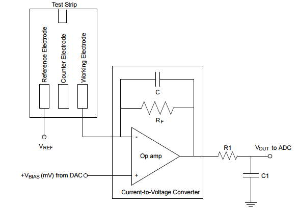
One application for example. When you're quantifying glucose in a blood sample on a test strip, you combine an enzyme, a electroactive mediator, and a blood sample. By applying some sort of a stimulus (a voltage) with maybe an DAC. The redox reaction emits a current in a certain direction with a certain magnitude.

So then one way for an embedded software engineering to analyze it, is by using a transimpedance amplifier (current-to-voltage) amplifier. Then read it in with an ADC.

enter image description here

Note this is just one example, and here's microchip's friendly App Notes for glucose design

\$\endgroup\$
7
  • \$\begingroup\$ sorry but i do not agree this way of explanation. consider a BJT common emitter amplifier. What if I know both input current and voltage? Will it be voltage in or current in??? \$\endgroup\$
    – user16307
    Commented Jan 22, 2016 at 11:57
  • \$\begingroup\$ You have to ask yourself what sort of linearity system this bjt common emitter amplifier offers. If the voltage in and voltage out are linearly correlated, then yes it's a voltage in and voltage out amplifier \$\endgroup\$
    – Iancovici
    Commented Jan 22, 2016 at 12:01
  • \$\begingroup\$ "It's because the voltage output is, ideally, linearly correlated to the current input." If input current and voltage are also linear what will we do? \$\endgroup\$
    – user16307
    Commented Jan 22, 2016 at 12:02
  • 1
    \$\begingroup\$ Then you my friend have discovered how to amplify power \$\endgroup\$
    – Iancovici
    Commented Jan 22, 2016 at 12:03
  • \$\begingroup\$ you dont get my point. Im saying if input current and input voltage are also linear it means both are linear with the output voltage. What do you say about CE transistor amplifier? is it current in or voltage in? \$\endgroup\$
    – user16307
    Commented Jan 22, 2016 at 12:05
0
\$\begingroup\$

The inputs and outputs are named with respect to what is the signal-carrying property.

So an ideal voltage-in voltage-out amplifier makes the promise my output voltage will be gain times the input voltage, I will supply any current there necessary to keep it so, and this is independent of whatever current enters my input.

Then, an ideal current-in current-out amplifier will instead expect that the current entering its input is the signal, so it promises my output current will be gain times the input current, I will drive the output voltage to whatever value necessary to keep it so, and this is independent of the voltage in my inputs.

Note that the other property, i.e. current for voltage input and so on, is always unspecified, it is whatever necessary to satisfy to specified property.

The mixed combinations should obvious from these examples.

A major technical difference caused by what does the amplifier promise to do, is that the ideal input impedance of a voltage-in amplifier is infinite so no current is needed to drive it, whereas the ideal input impedance of a current-in amplifier is zero, such that an arbitrarily small voltage can be used to provide the input current. Conversely, the ideal output impedance of a voltage out amplifier is zero, so that it provides any amount of current without a change in voltage, whereas the ideal output impedance of a current-out amplifier is infinite, such that it only needs infinitely small adjustments of voltage to supply the output current.

\$\endgroup\$

Your Answer

By clicking “Post Your Answer”, you agree to our terms of service and acknowledge you have read our privacy policy.

Not the answer you're looking for? Browse other questions tagged or ask your own question.