0
\$\begingroup\$

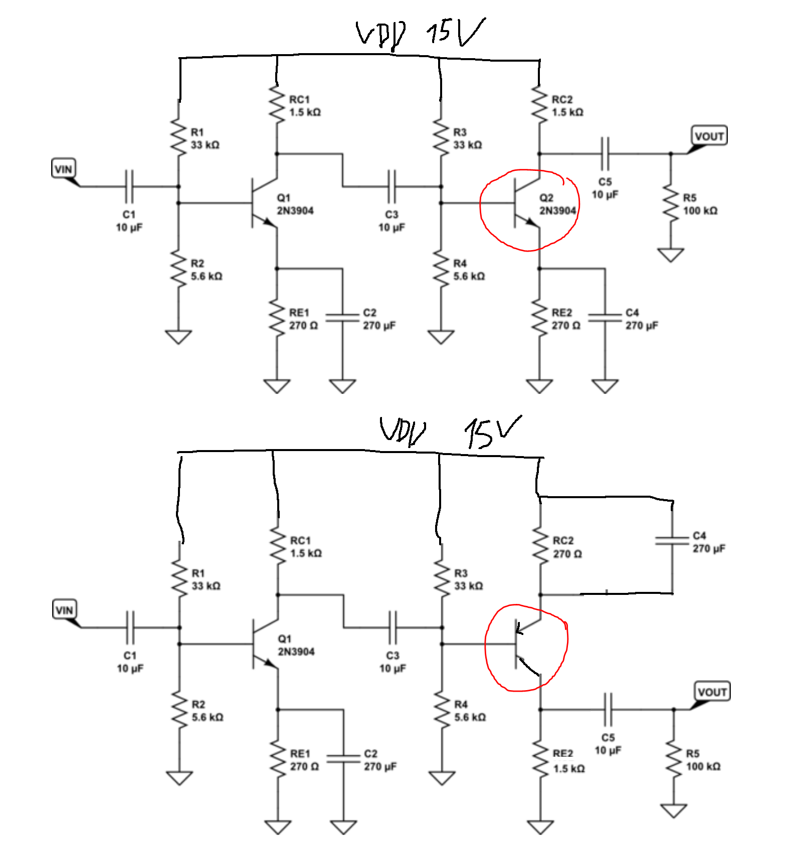
How would you choose NPN or PNP for the second stage amplifier like the one below? What are the advantages and disadvantages of them?

I see that both NPN and PNP can do the job.

I understand that they're different in that one is AC coupled and the other one is DC coupled, but they're just examples and could use the same type of coupling.

Also assume that the second stage is also an amplfier stage instead of a voltage or current buffer.
EDIT: I redrew the image as the suggestion by Andy. Please ignore the biasing as I haven't recalculated it and just assume that they have the correct biasing.

enter image description here

Image from:

BJT 2 stage amplifier

\$\endgroup\$
9
  • \$\begingroup\$ 1st circuit is low quality and not really a practical useful circuit. The 2nd circuit is not comparable with the first and is poorly biased for any potential load on the output. You need much better examples if you want a comparison. \$\endgroup\$
    – Andy aka
    Commented Sep 13, 2021 at 8:30
  • 2
    \$\begingroup\$ Correctly designed, both NPN and PNP will work in the second stage of an amplifier. The circuits you post are little more than demonstrations that you can achieve gain with a 2 stage amplifier. Distortion and the inability to drive practical loads would prevent them from being used seriously. \$\endgroup\$
    – Neil_UK
    Commented Sep 13, 2021 at 8:42
  • \$\begingroup\$ @Andyaka actually I tried to focus on the topology instead so I didn't check the bias point and coupling caps etc. \$\endgroup\$
    – emnha
    Commented Sep 13, 2021 at 10:09
  • 1
    \$\begingroup\$ One argument for a PNP is potentially lower noise (due to lower base spreading resistance). However to get the benefit, you would use it as the first stage; noise sources have much less impact after the first stage gain. \$\endgroup\$
    – user16324
    Commented Sep 13, 2021 at 13:53
  • 1
    \$\begingroup\$ @tobalt for example compare dicks-website.eu/low_noise_amp_part3/part3.html with dicks-website.eu/low_noise_amp_part5/part5.html but I am surprised by the (NPN) ZTX851 series. Note their astonishingly low Rbb! \$\endgroup\$
    – user16324
    Commented Sep 13, 2021 at 18:39

1 Answer 1

0
\$\begingroup\$

If you use an NPN Common Emitter first stage, its output (collector) cannot drop below \$V_{in} - V_D\$, where \$V_D\approx0.6V\$ is a diode drop. In particular, it cannot reach very close to Ground (assuming the input is somewhere midway between the supplies).

Therefore, a PNP is often a better match for a follow up stage, because you can use very small (or no) emitter resistors with it. The reason is because of the different input voltage requirements of a PNP or NPN second stage, respectively: As stated before, the output voltage of the (e.g.) NPN common emitter first stage is rather high. If you place another NPN after it, you need to level shift the voltage because the second NPN wants a low input voltage near its emitter (e.g. GND). For AC signals, you can do the level shift with a capacitor (i.e. AC coupling) but for DC signals you would need to bias the second NPN in a way that its emitter never goes near GND. With a PNP in the second stage, none of this is needed and you can just slam it right there, without any gate or emitter resistors.

As suggested by @DavideAndrea , the same arguments hold when the first stage is PNP. In that case, the second stage is simpler done using an NPN.

\$\endgroup\$
6
  • \$\begingroup\$ I see no basis for your statements. Indeed, on the contrary, everything that can be done with an NPN can also be done with a PNP, just by mirroring the circuit upside-down. And vice-versa. The only reason to use NPN's is convention. The selection of a PNP or an NPN is more likely due to parts availability within a given product. In high-power applications, the performance of an NPN can be better than for a PNP of a given size, but OP's circuit is not high-power. \$\endgroup\$ Commented Sep 13, 2021 at 13:52
  • 1
    \$\begingroup\$ @DavideAndrea Sure PNP/NPN can be swapped. All I am saying is that if your first stage is e.g. NPN, then it is simpler to use PNP for the second stage. Of course, you can make the first stage PNP, and then it will be simpler to follow up with an NPN. Of course you can also use all transistors of the same type (e.g. NPN) but then you will face more restríctions, e.g. the need for AC coupling between stages, which in turn forbids passing DC signals. \$\endgroup\$
    – tobalt
    Commented Sep 13, 2021 at 14:46
  • \$\begingroup\$ What is VD here? Could you the explanation why using all transistors of the same type requires coupling AC but different types does not? \$\endgroup\$
    – emnha
    Commented Sep 13, 2021 at 18:09
  • \$\begingroup\$ @anhnha VD is a diode drop. As I wrote the output voltage of the NPN common emitter stage is rather high. If you place another NPN after it, you need to level shift the voltage because the second NPN wants a low input voltage near GND. For AC signals, you can do the level shift with a capacitor (i.e. AC coupling) but for DC signals you would need to bias the 2nd NPN in a way that its emitter never goes near GND. With a PNP in the second stage, none of this is needed and you can just slam it right there, without any gate or emitter resistors. \$\endgroup\$
    – tobalt
    Commented Sep 13, 2021 at 18:22
  • 1
    \$\begingroup\$ @anhnha To be honest, I am not sure about this open-loop amplifier, but in closed-loop, the output voltage of Q1 would move close to the emitter of Q2. The excess voltage would drop over Q1 itself. \$\endgroup\$
    – tobalt
    Commented Sep 13, 2021 at 19:02

Your Answer

By clicking “Post Your Answer”, you agree to our terms of service and acknowledge you have read our privacy policy.

Not the answer you're looking for? Browse other questions tagged or ask your own question.