0
\$\begingroup\$

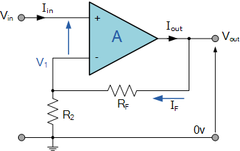
I have an op-amp design same with the picture seen below with TLC271.I have an analog sensor that goes as Vin. I am giving 3.3V from an arduino to power it. And reading values from an analog pin.

The problem is that the output gives between 0mV-8mV while sensor and resistors are connected.

r2=220 ohm| rf=22k ohm| sensor gives output between 0-200 mV

enter image description here

*Image taken from http://www.electronics-tutorials.ws/opamp/opamp_3.html

*I also have a zigbee module connected to arduino and a 5V 1A powerbank which powers the arduino.

\$\endgroup\$
6
  • \$\begingroup\$ What voltages are powering the OpAmp? 3.3V and ground? Good luck with that... \$\endgroup\$
    – Ecnerwal
    Commented May 20, 2016 at 18:04
  • \$\begingroup\$ Pin 8 of this device needs to be connected to Vcc, midrail or ground and not left floating I believe. \$\endgroup\$
    – Andy aka
    Commented May 20, 2016 at 18:05
  • \$\begingroup\$ Yes, but what is the problem with that. It is a single input op-amp and datasheet says it requires min 3V. \$\endgroup\$
    – bcan
    Commented May 20, 2016 at 18:06
  • \$\begingroup\$ I will try it now Andy, it sounds valid. \$\endgroup\$
    – bcan
    Commented May 20, 2016 at 18:07
  • \$\begingroup\$ Do you have a commercial or industrial grade? Vdd Min is 3V and 4V respectively. According to the Diodes Inc datasheet. \$\endgroup\$
    – Tyler
    Commented May 20, 2016 at 18:07

2 Answers 2

3
\$\begingroup\$

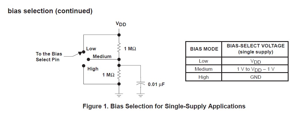
The data sheet says pin 8 (bias select) needs to be connected as shown below: -

enter image description here

A 3V3 power supply is OK as is the way you have connected R2 so ignore the other answer.

\$\endgroup\$
2
  • \$\begingroup\$ so should i directly feed bias pin with vdd or i need to put those resistors and caps too? \$\endgroup\$
    – bcan
    Commented May 20, 2016 at 18:17
  • \$\begingroup\$ You should decide what op-amp performance you want by reading the data sheet and choose low, medium or high bias. You only need the two resistors and a capacitor if you choose medium. \$\endgroup\$
    – Andy aka
    Commented May 20, 2016 at 18:20
0
\$\begingroup\$

Looking at the datasheet for the TLC271, I see that the minimum supply volyage is 3V. That is most probably your problem. You are going to have to use a higher voltage, eg 5V.

Then we have the problem of biasing of the opamp. You cannot just stick 5V and earth on there if you want any negative swing on the output. You need to do a bit more reading on the subject, there is plenty of information about this out there.

\$\endgroup\$
2
  • \$\begingroup\$ He's using a 3V3 supply - since when was that less than 3V? Also who says he wants a negative swing on the output? \$\endgroup\$
    – Andy aka
    Commented May 20, 2016 at 18:11
  • \$\begingroup\$ That could be nominal or drop under load - it would depend on the Ardiuno module he´s using. Maybe he needs to measure that just to check. In any case, he has a 5V 1A supply available there, so better just to use that. \$\endgroup\$
    – F. Bloggs
    Commented May 20, 2016 at 18:29

Your Answer

By clicking “Post Your Answer”, you agree to our terms of service and acknowledge you have read our privacy policy.

Not the answer you're looking for? Browse other questions tagged or ask your own question.