0
\$\begingroup\$

pH sensor input

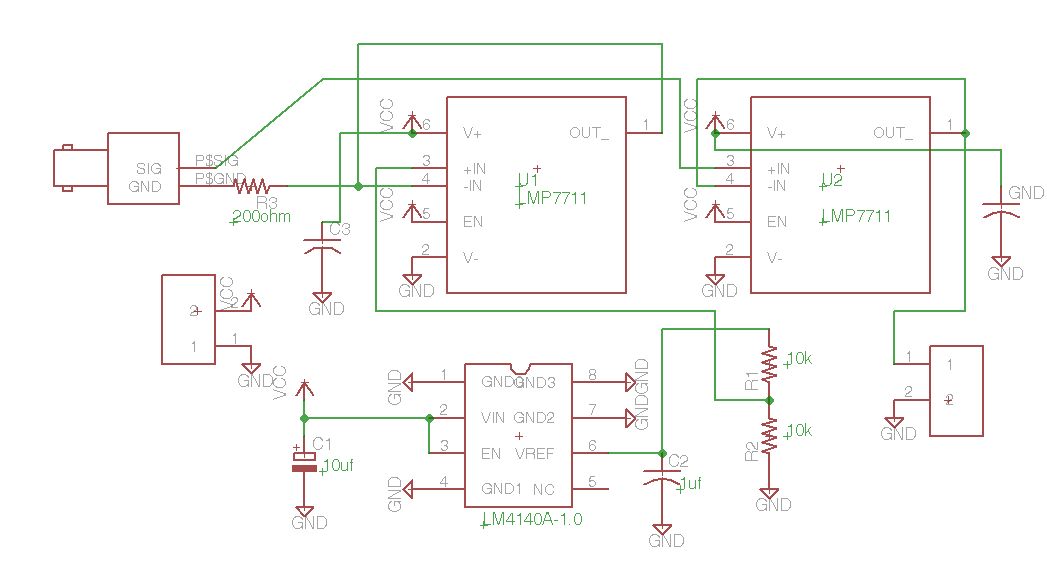
The circuit given above is pH sensor buffer circuit, picture taken from here. This circuit have pH sensor input and gives an output that can be read by multimeter which is U2's OUT_ pin . U1 is here to add some offset voltage to ground provided by LM4140 IC. This circuit's basic design was discussed in here.

Q1: What R3 (200 ohm) do here? They say its needed to isolate sensor input capacitance (i think capacitance is occurred due to cable's impedance).

Q2: Why only P$GND is connected with serial resistor? Isn't it also necessary do same thing on P$SIG?

Q3: What will be done to out signal if there is no R3 when needed and there is R3 even no needed?

\$\endgroup\$
1
  • 1
    \$\begingroup\$ ok. i will edit again \$\endgroup\$
    – user30878
    Commented Feb 26, 2015 at 13:47

2 Answers 2

2
\$\begingroup\$

Q1 - The discussion which established the need for R3 was wrong. As has been mentioned, a lot of op amps don't like to drive large capacitances to ground, and pH sensors often have large cable capacitances. However, in this circuit neither side of the sensor is connected to ground, so strictly speaking R3 is unnecessary.

There is an exception to this. Just using a pair of wires or a regular cable to connect the sensor will be likely to pick up noise, particularly mains frequency. In this case, it would make sense to use shielded cable, with the shield connected to ground. If this is true, R3 would be a good idea. This would mean that the sensor would be shown as having 3 connections (SIG, GND, and SHLD), not 2, so it does not obviously apply to your circuit. If you build it, and it seems OK sitting on the bench, but it goes crazy when you pick up the sensor, you need to think about it.

Q2 - The sensor needs a way to distinguish between the two leads. If you connect the GND line to ground, the SIG line will have a positive output. If you were using op amps with split supplies (both + and -) you could connect GND to ground and would not need the LM4140 or U1 at all. So the GND line is not NECESSARILY used as a ground connection. But, like I say, you don't need R3 in the circuit as shown.

Q3 - If R3 is not needed, but you provide it anyways, it will cause a very, very small reduction the sensitivity of your circuit, but this is not something you need to worry about.
\$\endgroup\$
5
  • \$\begingroup\$ comment to the Q2: This circuit is single supplied so it needs an offset voltage. However i'm confused about applying offset voltage to the reference electrode. There are two ways too for offset voltage, it can be added after first buffer op-amp with another op-amp and a ref. voltage supply or can be added to buffer op-amp directly with a ref. voltage supply i think. \$\endgroup\$
    – user30878
    Commented Feb 26, 2015 at 14:38
  • \$\begingroup\$ Sorry, no. The offset needed is an offset from ground. This is provided by the LM4140, R1 and R2, and this offset is buffered by U1. You do not need any further offsets. \$\endgroup\$ Commented Feb 26, 2015 at 14:46
  • \$\begingroup\$ comment to Q1: In a single supplied system, you say it will be good if shield connected to ground, and pH probe's GND is connected to the R3 right? \$\endgroup\$
    – user30878
    Commented Feb 26, 2015 at 15:26
  • \$\begingroup\$ However why i can't add offset voltage using a second amplifier as a summing amplifier? \$\endgroup\$
    – user30878
    Commented Feb 26, 2015 at 15:31
  • \$\begingroup\$ @user30878 - That's correct about the shield BUT you may not need it. And you can add an offset with another op amp. But why would you want to? If you look at the app note, and figure out what the circuit is doing, you'll see that the nominal output for the circuit is 0 to 1 volt. Why would you need an offset? \$\endgroup\$ Commented Feb 26, 2015 at 19:36
3
\$\begingroup\$

Notice the asymmetry. P$GND is driven by an output, presumably with a reference voltage from U1. Presumably U1 isn't suitable for driving capacitive loads, a lot of opamps can be unstable driving capacitive loads at unity gain.

So without R3, U1 may oscillate instead of generating a steady voltage reference.

P$SIG is only an input, so has no such problem.

\$\endgroup\$
0

Your Answer

By clicking “Post Your Answer”, you agree to our terms of service and acknowledge you have read our privacy policy.

Not the answer you're looking for? Browse other questions tagged or ask your own question.