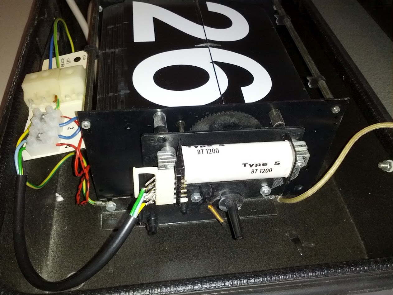
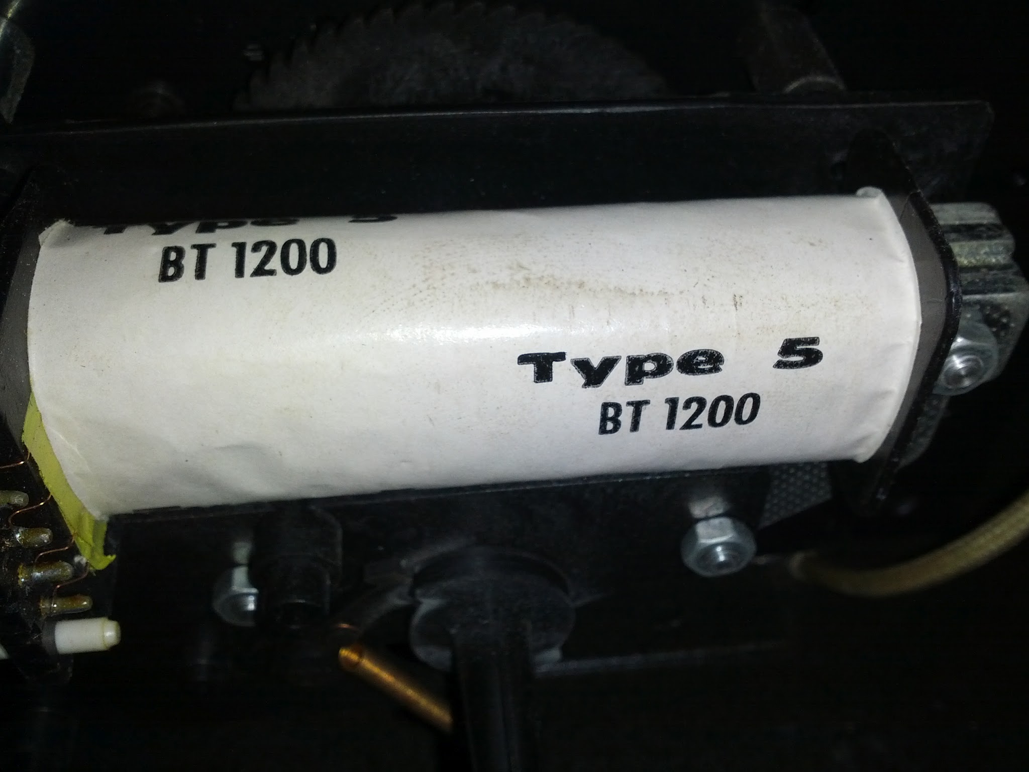
It's effectively an electric motor - possibly driven at mains frequency and possibly an escapement release solenoid - but maybe effectively both. Probably it provides he complete driving power for the flip action but the double lobe cam (see below) suggests triggering at regular intervals. If here is no other timing or driving mechanism then it may have been run as a "slave" with control pulses sent via the visible wiring from a central controller.
In his photo from your website you can see a general view of how it is associated with the shaft drive.

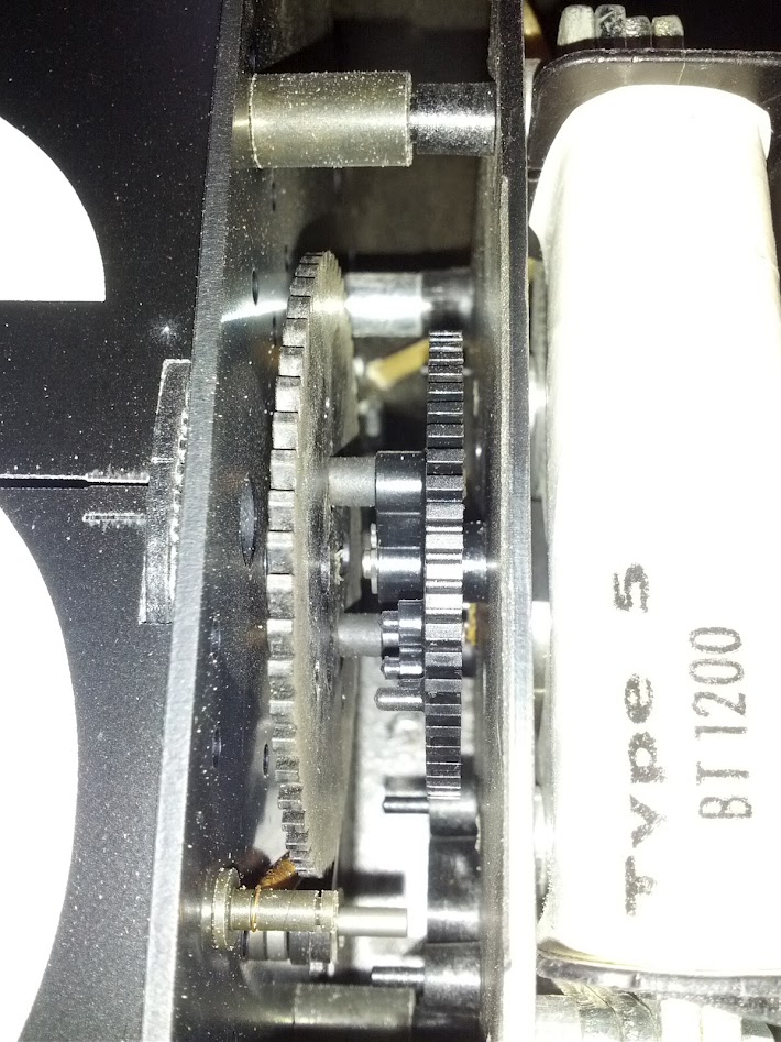
And here you can see the reduction gear train from the motor shaft to the flipping shaft.

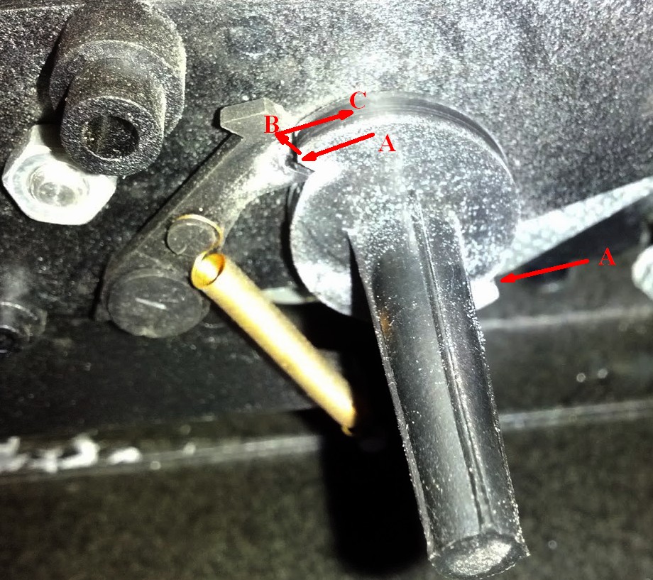
This cam ensures an identical action every time a pulse is received.
There is a 2 lobe can face at A and A that traps the rotating cam against the lever. When a pulse is received the lever moves in direction B and he canm is free to rotate. The lever effectively travels in direction B but of course he actual motion is the shaft rotating anti0clockwise. After half a turn the shaft is again trapped against a vertical face.
If the rotating shaft is turned backwards (clockwise) it is not trapped by the cam faces. This would eg allow the drum to be turned backwards to set the time.
This mechanism may work with the same pulses used to control time clocks in older analog dial systems - used in eg British Railway Stations long ago I think - and many other such locations.


