Enough information has arrived that some answers can be suggested, I think.
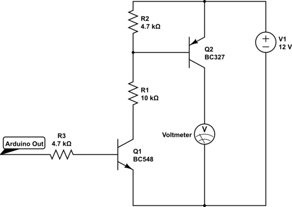
You don't really need to understand the behavior of your voltmeter's measurement without a load present. Your circuit doesn't need to manage or care about the case where there is no load. There always will be a load there. And the load itself will make the collector voltage predictable, anyway. So digging into the details here is more a matter of intellectual curiosity than anything else.
Your question does propose it, granted. And I'm not going to be able to actually answer it, because I 100% agree with Spehro's answer. Instead, I'm going to tell you that you shouldn't care about knowing the exact reason for your observation. Not right now. Because you have a different problem with your circuit that is far more important and needs to be addressed.
That said, if you actually want to track down the behavior entirely for intellectual reasons, then I suggest that you start a different question where you eliminate the LED drive aspect and focus 100% on the question of your observation. But to do that, you will be focusing on possible parasitics, possible damage (for example, BJTs which have experienced reverse biased \$V_{BE}\$ in excess of 5 or 6 V and may have been 'punctured'), and rather obscure behaviors of BJTs which are not in the datasheets or perhaps may not even be captured fully in the models usually found in Spice and are rarely of concern to engineers (though they may be of interest to solid state physicists.) But you will probably need better equipment on hand, as well. Or, have well-characterized the equipment you do have.
For example, in one experiment you may want to slightly vary the load presented by your voltmeter, to see how the voltage changes with nearby changes in net impedance to get an idea of the local slope. Then vary it more to see if there is a shape to that behavior, as well.
Your wiring methods might also have to come under very close scrutiny.
But all that would be an entirely different question, really.
Back to the issue at hand. You need a circuit to provide at least \$450\:\textrm{mA}\$ of current compliance while providing \$12\:\textrm{V}\$ to the LED module/whatever.
The BC327 PNP may not be the best choice. Yes, a datasheet does say up to \$800\:\textrm{mA}\$ on the Absolute Maximum Ratings area. But that's not a recommendation. It's an Absolute Maximum! Take a look at the Electrical Characteristics table where you can see that with \$I_c=500\:\textrm{mA}\$, the worst case \$\vert V_{CE\left(sat\right)}\vert \approx 700\:\textrm{mV}\$. If so, and ignoring the \$V_{BE\left(sat\right)}\cdot I_C\$ dissipation for now, you'd already have \$0.7\:\textrm{V} \cdot 0.45\:\textrm{A}= 315\:\textrm{mW}\$. That may seem okay, but I recently saw a TO-92 package sporting \$325\:\frac{^{\circ}\textrm{C}}{\textrm{W}}\$ (and they seem to always be no better than \$200\:\frac{^{\circ}\textrm{C}}{\textrm{W}}\$, which is probably often optimistic), which would imply an increase in temperature of \$\approx 100\:^{\circ}\textrm{C}\$. Not so good.
It might be worth finding a different BJT. Perhaps one packaged in a TO-220 (or similar.) Just to be on the safer side. But I also don't know if you are using a duty cycle that is low enough to seriously impact the dissipation. If you are, then perhaps this is an okay choice for pulsed operation.
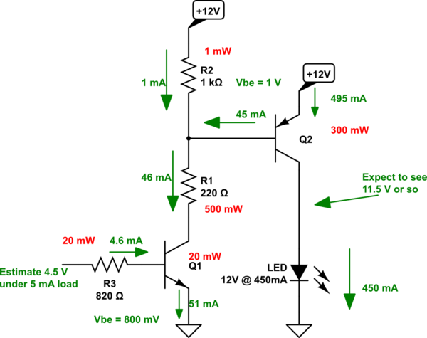
Broadly speaking, using your topology, the circuit should be designed about like this:

simulate this circuit – Schematic created using CircuitLab
This is the ON case, of course. You can see that there's a number of small details included in the design. I won't belabor the details further, except to say that if you include various resistor variations about their nominal value, and BJT parameter variations as well, the circuit will still work fairly closely to the design specs there.
You can see that \$R_1\$ does need to dissipate some power. Should be at least \$1\:\textrm{W}\$ in size.


