1
\$\begingroup\$

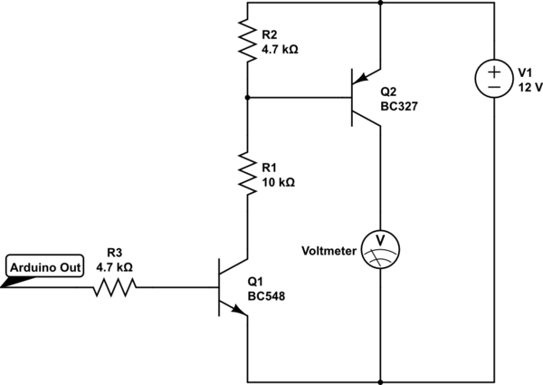
I am using a simple circuit to drive a 12V LED with Arduino. I have used this circuit successfully in past. I am using NPN-PNP combination to drive a load which needs more Voltage than Arduino's HIGH voltage (i.e. 5V). Today, I noticed that my voltmeter reads 10.2V on Arduino LOW and 12V on Arduino HIGH OUTPUT. I had no load attached to it when I measured the behavior. Well, it serves my purpose when I put the LED in place of voltmeter - since the LED has a forward voltage of 12V, it turns ON and OFF with Arduino HIGH and LOW signal.

But, my question is why do I see 10.2V when Arduino output is LOW? I am a newbie. So may be I am expecting something wrong. Shouldn't I get 0V when Arduino is LOW? Or is this switch only good for Controlling Current, not Voltage? Or is it because I was measuring the Collector Voltage with No-Load attached?

schematic

simulate this circuit – Schematic created using CircuitLab

\$\endgroup\$
9
  • 2
    \$\begingroup\$ The voltmeter represents an extremely high resistance. It produces a 'voltage' reading (really a current reading) with extremely low currents (leakage). Repeat the measurement with a normal 'load' - say 10k fixed resistor and it should all work fine.. \$\endgroup\$ Commented Oct 20, 2016 at 19:14
  • \$\begingroup\$ Well, I guess so. Everything looks fine when there is a meaningful load. My question is - is this behavior expected? Should I expect to see around 10V on Arduino LOW, when no load is present? \$\endgroup\$
    – sribasu
    Commented Oct 20, 2016 at 19:22
  • \$\begingroup\$ You can simulate your circuit in Circuit Lab (you have 95% of the work done already). Put a clock signal where the Arduino Output is, set to to something reasonable (1 Hz) add a resistor in parallel to the Voltmeter and you will be able to confirm your understanding of the function of the circuit. Your real world circuit doesn't match, so it sounds like something has burned up or is not wired correctly. \$\endgroup\$
    – Tyler
    Commented Oct 20, 2016 at 19:25
  • 1
    \$\begingroup\$ What currents do your 12 V LED require? (Just curious about your resistor choices.) \$\endgroup\$
    – jonk
    Commented Oct 20, 2016 at 19:36
  • \$\begingroup\$ It's a Power LED. Draws 450mA at 12V. I didn't add any current limiting resistor although I know it's not wise to connect the LED directly :) \$\endgroup\$
    – sribasu
    Commented Oct 20, 2016 at 19:40

3 Answers 3

2
\$\begingroup\$

Enough information has arrived that some answers can be suggested, I think.

You don't really need to understand the behavior of your voltmeter's measurement without a load present. Your circuit doesn't need to manage or care about the case where there is no load. There always will be a load there. And the load itself will make the collector voltage predictable, anyway. So digging into the details here is more a matter of intellectual curiosity than anything else.


Your question does propose it, granted. And I'm not going to be able to actually answer it, because I 100% agree with Spehro's answer. Instead, I'm going to tell you that you shouldn't care about knowing the exact reason for your observation. Not right now. Because you have a different problem with your circuit that is far more important and needs to be addressed.

That said, if you actually want to track down the behavior entirely for intellectual reasons, then I suggest that you start a different question where you eliminate the LED drive aspect and focus 100% on the question of your observation. But to do that, you will be focusing on possible parasitics, possible damage (for example, BJTs which have experienced reverse biased \$V_{BE}\$ in excess of 5 or 6 V and may have been 'punctured'), and rather obscure behaviors of BJTs which are not in the datasheets or perhaps may not even be captured fully in the models usually found in Spice and are rarely of concern to engineers (though they may be of interest to solid state physicists.) But you will probably need better equipment on hand, as well. Or, have well-characterized the equipment you do have.

For example, in one experiment you may want to slightly vary the load presented by your voltmeter, to see how the voltage changes with nearby changes in net impedance to get an idea of the local slope. Then vary it more to see if there is a shape to that behavior, as well.

Your wiring methods might also have to come under very close scrutiny.

But all that would be an entirely different question, really.


Back to the issue at hand. You need a circuit to provide at least \$450\:\textrm{mA}\$ of current compliance while providing \$12\:\textrm{V}\$ to the LED module/whatever.

The BC327 PNP may not be the best choice. Yes, a datasheet does say up to \$800\:\textrm{mA}\$ on the Absolute Maximum Ratings area. But that's not a recommendation. It's an Absolute Maximum! Take a look at the Electrical Characteristics table where you can see that with \$I_c=500\:\textrm{mA}\$, the worst case \$\vert V_{CE\left(sat\right)}\vert \approx 700\:\textrm{mV}\$. If so, and ignoring the \$V_{BE\left(sat\right)}\cdot I_C\$ dissipation for now, you'd already have \$0.7\:\textrm{V} \cdot 0.45\:\textrm{A}= 315\:\textrm{mW}\$. That may seem okay, but I recently saw a TO-92 package sporting \$325\:\frac{^{\circ}\textrm{C}}{\textrm{W}}\$ (and they seem to always be no better than \$200\:\frac{^{\circ}\textrm{C}}{\textrm{W}}\$, which is probably often optimistic), which would imply an increase in temperature of \$\approx 100\:^{\circ}\textrm{C}\$. Not so good.

It might be worth finding a different BJT. Perhaps one packaged in a TO-220 (or similar.) Just to be on the safer side. But I also don't know if you are using a duty cycle that is low enough to seriously impact the dissipation. If you are, then perhaps this is an okay choice for pulsed operation.

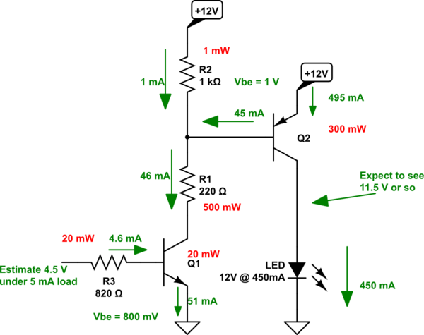
Broadly speaking, using your topology, the circuit should be designed about like this:
schematic

simulate this circuit – Schematic created using CircuitLab

This is the ON case, of course. You can see that there's a number of small details included in the design. I won't belabor the details further, except to say that if you include various resistor variations about their nominal value, and BJT parameter variations as well, the circuit will still work fairly closely to the design specs there.

You can see that \$R_1\$ does need to dissipate some power. Should be at least \$1\:\textrm{W}\$ in size.
\$\endgroup\$
6
  • \$\begingroup\$ Nice job, and graphics, but minus 1 because that entire irrelevant rant has nothing to do with the OP's question. \$\endgroup\$
    – EM Fields
    Commented Oct 20, 2016 at 21:09
  • \$\begingroup\$ @EMFields Thanks. I've grown to expect your distaste of my writing style. You should actually go read the rest of my answers and have fun with them, as well. Enjoy. \$\endgroup\$
    – jonk
    Commented Oct 20, 2016 at 21:13
  • \$\begingroup\$ It's not critique of style, at all, since we all have our own ways of communicating, it's about context and content. \$\endgroup\$
    – EM Fields
    Commented Oct 20, 2016 at 21:22
  • \$\begingroup\$ @EMFields I suspect that also is a matter of 'ways of communicating.' I was addressing a desire expressed by the OP elsewhere, as part of it. It's how I do things, sometimes. Not always. But I'm unlikely to change. So we will just have to continue disagreeing. Which actually is quite fine with me. \$\endgroup\$
    – jonk
    Commented Oct 20, 2016 at 21:25
  • \$\begingroup\$ Where does your perceived position of dominance allow you go make rules? \$\endgroup\$
    – EM Fields
    Commented Oct 20, 2016 at 22:00
0
\$\begingroup\$

I would suspect something is going on with your circuit- either the transistor Q2 is damaged (or very hot) or the Arduino output is not really low. Or perhaps R2 is missing or open circuit.

Typical CE leakage for a BC327 is only 2nA at Ta=25°C which will show ~20mV on a typical voltmeter with 10M input impedance. If you are using an expensive bench top meter such as an Agilent 34401 set to 10G input impedance then it might make sense.

\$\endgroup\$
13
  • \$\begingroup\$ Q2 is neither damaged, nor hot. I verified. And it works fine when on load. I am using a simple digital Multimeter to measure voltage. No special equipment as such. \$\endgroup\$
    – sribasu
    Commented Oct 20, 2016 at 19:21
  • 2
    \$\begingroup\$ @sribasu I completely agree with Spehro's answer, though. He's right that it would take a lot of input impedance to show the voltage you say you read, given tiny leakages and the circuit. But perhaps the answer here to you is that "it's not expected" but it's also in an area where the circuit isn't under design management, either. So it's not necessarily important unless you are serious about tracking down the behavior as a matter of gaining a detailed physical understanding for the observation. \$\endgroup\$
    – jonk
    Commented Oct 20, 2016 at 19:35
  • 1
    \$\begingroup\$ Your resistor value R1, as @jonk suspected, is way high for a 450mA load. It should be more like 500 ohms. And you should control the LED current with a resistor if there isn't one as part of the LED assembly. I would expect Q2 to be in some distress under those conditions - and it could be damaged. \$\endgroup\$ Commented Oct 20, 2016 at 19:44
  • 1
    \$\begingroup\$ @sribasu I understand that you think you want to understand it, but you really don't need to. Not for such a circuit. If you did want to manage this behavior, adding a resistor parallel to your load might be one approach. Then it would become predictable. But in practice this isn't important because the load itself makes the result predictable. The lack of a load is a situation that doesn't occur in practice. So you don't need to study it. \$\endgroup\$
    – jonk
    Commented Oct 20, 2016 at 19:47
  • 1
    \$\begingroup\$ Yes. Any time someone says "12 V LED" I start thinking now of those long strips or else of the high power modules. Either way, lots of current. His \$R_1\$ suddenly scared me and I wanted to know what he was really doing. \$\endgroup\$
    – jonk
    Commented Oct 20, 2016 at 19:49
0
\$\begingroup\$

In short, what you are seeing is due to leakage thru Q2.

Q2 is a good enough switch so that the LED load can be turned on and off. However, this switch isn't perfect. A little current will flow even when it is "off".

You didn't say anything about your voltmeter, so I'll assume it has 10 MΩ input resistance. That's a common value for a electronic voltmeter. Since you measured 10.2 V, we can compute the current from Ohm's law: (10.2 V)/(10 MΩ) = 1.02 µA.

That seems high. I just grabbed a random BC327 datasheet (Fairchild), and it lists the maximum leakage current as 100 nA. You're seeing 10x that.

My guess is that this transistor was previously abused. Higher than normal off-state leakage is a common soft failure mode.

Also check the other voltages and that Q1 is properly off. The digital control signal should be very close to 0 V. Q1 should be off to the extent you can measure it with your voltmeter. It's collector should be at the full 12 V supply level. Put the voltmeter between the 12 V supply and the collector of Q1 and it should read very close to 0 (not even a few millivolts).

\$\endgroup\$

Your Answer

By clicking “Post Your Answer”, you agree to our terms of service and acknowledge you have read our privacy policy.

Not the answer you're looking for? Browse other questions tagged or ask your own question.