3
\$\begingroup\$

I'm trying to implement a polarity protection using the P-MOSFET technique on a 30v DC circuit

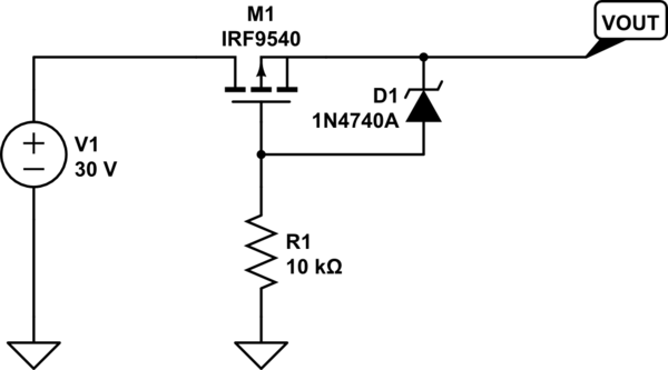
How can I protect the gate of a IRF9540N (Vgs 20v)?

I saw that I can use a voltage divider using 2 resistors or 1 resistor and 1 zenner?

Which one is the best?

How can I calculate the resistor values properly?

I saw this circuit on a Indestructables

schematic

simulate this circuit – Schematic created using CircuitLab

Thank you very much.

\$\endgroup\$
6
  • \$\begingroup\$ Actually use all three, two resistors and the zener, just to be safe. Technically either would work. For th resistor divider approach, assuming you don't need this to switch on very fast, high value resistors are fine to minimize current draw, e.g. in the 100k range or higher. You would select resistors to provide the Vgs at a comfortable level, so e.g. since this FET has threshold Vgs of 4V, set it to provide maybe 10V, i.e. 100k between gate and source, and 200k from gate to ground. If you use the zener, the zener clamps the Vgs voltage, while the resistor tries to pull the voltage... \$\endgroup\$
    – AngeloQ
    Commented Feb 6, 2017 at 3:27
  • \$\begingroup\$ to ground. The resistor should have a value high enough to avoid exceeding the current rating on the zener (100mA in this case), but again, it doesn't need to be that high, so probably 100k would work fine. So why use both (two resistors and a zener)? If there is some fault or soldering problem e.g. in the above circuit where the zener is not soldered properly to Vout, the Vgs would be exceeded. The same would be true if the high resistor of the divider was missing. MOSFETs have zero tolerance to Vgs beyond the max spec. Usually an extra resistor or zener is much less costly than a FET. \$\endgroup\$
    – AngeloQ
    Commented Feb 6, 2017 at 3:32
  • \$\begingroup\$ There is a possible way to blow the FET even if you do the gate source zener .Imagine that your circuit is in say a 24V truck .Then say that your protected output has lots of capacitance across it .This is not unreasonable perhaps it is a big car Audio system or maybe an inverter. Now say if the input volts drops quickly due to say starting the engine .The load capacitance will discharge through the P channel because it is still hard on .The spike current is only limited by the total circuit resistance which could be miliohms ,If the mosfet has a small size and a low on resistance then BANG \$\endgroup\$
    – Autistic
    Commented Feb 6, 2017 at 4:26
  • 1
    \$\begingroup\$ @Autistic, if there is that much capacitance, then inrush could be a big problem, too. OP would be well advised to consider both cases. \$\endgroup\$
    – user57037
    Commented Feb 6, 2017 at 4:39
  • \$\begingroup\$ It is plausible that the imaginary equipment with the big Cap has say an internal mosfet for inrush protect .BUT we are talking about outrush current .The imaginary internal mosfet could blow too.The diode is therefore more robust so when you place a fet across it to reduce volt drop you can sense the DS volts and shut down the gate to avoid runback . \$\endgroup\$
    – Autistic
    Commented Feb 6, 2017 at 4:45

1 Answer 1

3
\$\begingroup\$

The Zener is better for two reasons:-

  1. The Gate is clamped to a safe voltage no matter what the input voltage, whereas with a resistor divider Gate voltage continues to increase as input voltage increases.

  2. The Zener doesn't reduce Gate voltage when below its Zener voltage, so the FET will still be well turned on at low input voltages.

With resistors you need to balance the required Gate turn-on voltage against the voltage reduction required for protection. That limits the range of input voltages that the circuit can handle, and requires carefully chosen resistor values.

With a Zener, the resistor value just has to be high enough to not overheat the Zener or resistor, but low enough to provide adequate Zener bias current and to discharge the Gate rapidly if the supply voltage is suddenly reversed (so 10K is OK, but 10M might not be).

The 1N4740A is rated for 25mA nominal, but should work down to a bit less than 1mA. At 30V in the resistor has to drop 20V, so its value could range from at least 20V/25mA = 800Ω to 20V/1mA = 20k. At 10V in the FET will get almost the whole 10V so it will still be fully turned on.

With a resistor divider, to get 10V on the Gate one resistor has to drop 20V and the other 10V, thus dividing the input voltage by 3. The lower resistor then has to be twice the value of the upper one, ie. if R1 is 10k then (the resistor in place of) D1 must be 5k.

However at 10V the resistors will still divide the voltage by 3 so the FET will only get 3.3V - not enough to turn it on properly. This could be bad news if the power supply 'browns out' or the load draws a high surge current that momentarily drops the input voltage, as the partially turned on FET could dissipate high power and blow up.
\$\endgroup\$
1
  • \$\begingroup\$ I've done some tests using the zener and 10k resistor and it worked great. Why after 50v, connecting inverted, the circuit begin to pass some voltage? \$\endgroup\$ Commented Feb 6, 2017 at 21:55

Your Answer

By clicking “Post Your Answer”, you agree to our terms of service and acknowledge you have read our privacy policy.

Not the answer you're looking for? Browse other questions tagged or ask your own question.