1
\$\begingroup\$

Circuit

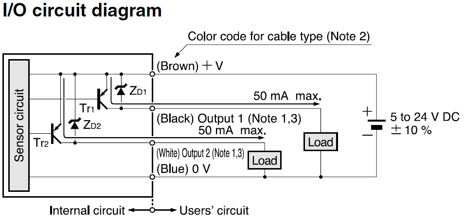
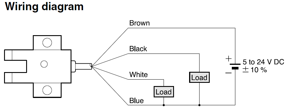
Consider the following U-Shaped Micro Photoelectric Sensor Panasonic PM-T54P with two PNP Open-Collector Transistor outputs:

Photoelectric Sensor Input/Output Circuit Diagram

Photoelectric Sensor Wiring Diagram

Photoelectric Sensor Output

I chose the supply voltage to be 12V DC. In the place of the two loads I want to place two voltage meters (to be more precise the NI 9401), which can endure a maximum voltage of 5V DC.

After some calculations, I came up with the following first schematic for Output 1 (the one for output 2 is identical, so I leave it out):

schematic

simulate this circuit – Schematic created using CircuitLab

Some explanations:

  • The connection to ground at the pull-down resistor R_GND is supposed to prevent a floating input into the NI 9401.
    It should be possible to get a switch into the schematic between V_A and V_In, which physically opens or closes the connection, but I did not know how to do this.
  • The resistance R_NI is supposed to limit the current into the NI 9401 to less than 250uA in case the circuit is compromised and the resistors R_A and R_GND are bridged, so that R_NI alone has to deal with the full 12V of V_A.

Questions

  1. Do I really need the connection to ground at R_GND? Can one tell from the internal circuit on the I/O circuit diagram if e.g. Output 1 will float or will have 0V if the transistor Tr1 is non-conducting?

  2. Let's assume that V_A rises due to a control error of the user up to 30V, but I still want exactly my 12V at V_In.
    Could I accomplish this task with a 12V Zener-Diode between V_A and V_In as shown in the circuit below?

  3. Finally I want an additional protection for V_Out, which should be capped at exactly 4.7V independently of what happens before it.
    Could I accomplish this task with a 4.7V Zener-Diode between R_NI and V_Out as shown in the circuit below?

This is my draft for both question 2 and 3:

schematic

simulate this circuit

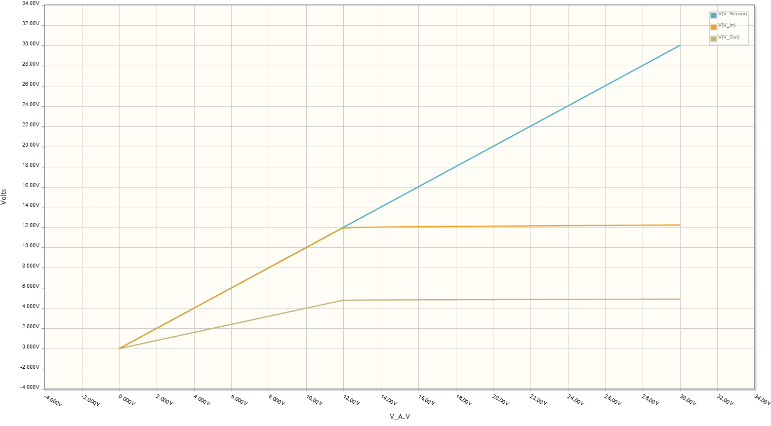
And here is the result for a DC Sweep of V_In between V_In = 0V and V_In = 30V. It seems to be OK, right?

Voltage Protection Result

Update

Now it states here that the input impedance of the NI 9401 is 47kOhm, so I tried to create a new schematic accordingly, based on the remarks from Bruce Abbott and rioraxe. Would that be correct?

schematic

simulate this circuit

Here's the result:

Voltage Plots Current Plot

\$\endgroup\$
5
  • \$\begingroup\$ I don't feel like reading through all this. \$\endgroup\$
    – 12Lappie
    Commented Feb 1, 2017 at 20:32
  • \$\begingroup\$ We're not sure if you are asking the right questions since the design requirements, all the fault conditions and test requirements are not clear. IT is a simple voltage switch with uncertainty on layout EMI problems and noise immunity needed. There is insufficient clarity need to define what is needed for all environments and possible fault conditions and all Input/function/output and environmental stresses and fault requirements ought to be summarized. \$\endgroup\$
    – D.A.S.
    Commented Feb 1, 2017 at 20:42
  • \$\begingroup\$ the Panasonic sensor provides redundant complementary switched low impedance outputs for Dark and light sensing operating over a wide range of 5 ~24V. Why introduce another supply of 10 15 to 24V with such uncertainty unless it could not be avoided, then introduce a messy diode resistor circuit that raises the resistance and thus lowers the immunity to noise? i.e. why not use 5v low impedance switches and redundancy? \$\endgroup\$
    – D.A.S.
    Commented Feb 1, 2017 at 20:52
  • 2
    \$\begingroup\$ "to be more precise the NI 9401" - The NI 9401 has TTL level digital inputs, with input current specified at +-250uA between 0V and 4.5V. If that really is what you have then I suspect it may need much lower driving impedance than 100k (250uA*100k = 25V!). \$\endgroup\$ Commented Feb 2, 2017 at 2:44
  • \$\begingroup\$ @BruceAbbott Thank you for the comment. Unfortunately I have never worked with sensors before, so I am in the dark about most stuff such as TTL and Digital Inputs. I created a new Update section to my question, could you please check if the circuit and its results make more sense now? Also, are the +-250uA input current maximal levels or should I try to provide a constant level of e.g. +250uA in the whole operational range between 0V und 4.5V? \$\endgroup\$
    – Discbrake
    Commented Feb 2, 2017 at 8:49

1 Answer 1

3
\$\begingroup\$

Going with some of your ideas, it could be just this:

schematic

simulate this circuit – Schematic created using CircuitLab

The 1.5k comes from 0.4V/250uA as pointed out by Bruce Abbott of the NI 9401 input requirement.

\$\endgroup\$
9
  • \$\begingroup\$ Thanks. Now I tried to adapt my schematic based on your answer in the last section "Update" of my question. Does that look better now? \$\endgroup\$
    – Discbrake
    Commented Feb 2, 2017 at 8:26
  • 1
    \$\begingroup\$ The input low threshold VIL for TTL is usually 0.8V, so set the resistor to pull below that. 0.4V is a common number that gives 0.4V of margin. My version looks better :), why all the extra stuffs. \$\endgroup\$
    – rioraxe
    Commented Feb 2, 2017 at 18:55
  • 1
    \$\begingroup\$ Looking up the NI 9401 Datasheet, on page 5: Input current \$\pm\$250 uA. What that means is that within the input voltage range of 0 to 4.5V, the NI 9401 input can source or sink up to 250uA. So the worst case calculation for the pull down would be when the input is sourcing 250uA, it must be of low enough resistance to pull the voltage to below certain threshold which was chosen to be 0.4V. The NI 9401 does not care how much current the resistor sinks when the output from the sensor is at 5V. \$\endgroup\$
    – rioraxe
    Commented Apr 11, 2017 at 0:15
  • 1
    \$\begingroup\$ page 5: Input current ±250 uA. The NI 9401 can be sourcing or sinking per the spec. The sensor cannot sink current per your "I/O Circuit Diagram" at the top. So when the sensor output is low, the sensor is not sourcing or sinking any current, the pull down has the task for ensuring a low level. The sensor can source up to 50mA. So when the sensor is high, it would source at 12V (your chosen supply voltage) of up to 50mA. The resistor divided can be chosen to give the desired voltage. \$\endgroup\$
    – rioraxe
    Commented May 10, 2017 at 19:18
  • 1
    \$\begingroup\$ When the sensor output is high, while ignoring the NI9401, the current through the resistor divider would be 12V/(2.2K+1.5K) = 3.2mA. Now back track and compare that to the NI9401 ±250uA input current, which is less than 10%. The possibility of NI9401 sourcing +250uA can be ignored because it cannot source current above 5V (its supply voltage). If the NI9401 sinks -250uA, it would reduce the divider output voltage by less than 10%, which would still be a solidly high level with a big margin. \$\endgroup\$
    – rioraxe
    Commented May 10, 2017 at 19:29

Your Answer

By clicking “Post Your Answer”, you agree to our terms of service and acknowledge you have read our privacy policy.

Not the answer you're looking for? Browse other questions tagged or ask your own question.