3
\$\begingroup\$

Most today used switching regulator ICs that I've seen have some kind of feedback voltage pins. I think I've pretty understood the way it works:

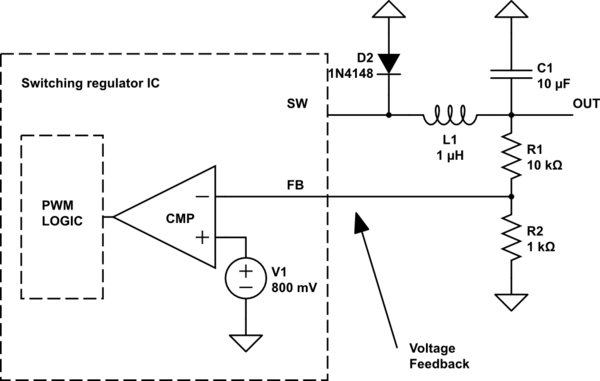
A resistor divider from output to ground is created to fed back some portion of the output voltage to the feedback amplifier that will generate a voltage for the PWM generator logic.
schematic

simulate this circuit – Schematic created using CircuitLab

The voltage will be compared to some internal reference voltage, 800mV in this example. If the feedback voltage is higher than that reference the PWM generator will be turned off, otherwise the duty cycle will be adjusted accordingly.

My goals are:

  • Trying to build a power supply with the ability to electronically control the output voltage.
  • Trying to understand whats going on

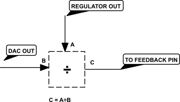
My question is, what is the best way not to use this static resistor divider but to use some proportional voltage? My Idea was to generate a reference voltage (my desired regulator output voltage) with help of a micro controller and an DAC. If I know the required proportion of R1 to R2 to generate a specific voltage I can derive a division factor like:

\$V_{FB} = \frac{V_{O}}{N}\$

The division factor N is a function of output voltage in most cases as I found out. However I have no idea to build that kind of circuit. Should I use logarithmic opamps for that kind of mathematical division or is there a better solution which I have not even considered? May be there is a much simpler solution?

Edit: My basic idea
schematic

simulate this circuit

This kind of operation would be possible either with two expensive logarithmic op-amps or by very expensive special purpose circuits. Because it use analog voltages without taking a detour over ADC/DAC, latency would be low enough. But as I said I'm not sure if there are better ways.

\$\endgroup\$
14
  • \$\begingroup\$ This is probably doable without screwing with the control loop. More to come later. \$\endgroup\$
    – Matt Young
    Commented Apr 4, 2017 at 22:46
  • 1
    \$\begingroup\$ The Vout is controlled by (1+ R ratio )* Vref. You could use R2 DAC to program Voltage. \$\endgroup\$
    – D.A.S.
    Commented Apr 4, 2017 at 23:10
  • 1
    \$\begingroup\$ @StainlessSteelRat Yes reading by ADC would be one idea, but I was more thinking of analog math operations because ADC/DAC would generate to much latency. In the end, the voltage will not be stable and accurate enough. \$\endgroup\$
    – bkausbk
    Commented Apr 5, 2017 at 6:37
  • 2
    \$\begingroup\$ A few days ago, I answered a question like OP's. May help. \$\endgroup\$ Commented Apr 5, 2017 at 8:27
  • 1
    \$\begingroup\$ Rohat's answer gives an excellent suggestion. There are also reference designs from e.g. TI: ti.com/lit/ug/tidu533/tidu533.pdf - you can get ICs that are directly programmable over I2C. \$\endgroup\$
    – pjc50
    Commented Apr 5, 2017 at 8:29

3 Answers 3

1
\$\begingroup\$

Unfortunately I can't elaborate on how to determine the resistor values because I don't remember but there is 1 or 2 places online that at least did tell you the equations.

But what you can do(if I understand what you are asking for) is to simply tie a 3rd resistor to the feedback pin and then drive the other end of that resistor with a voltage output DAC.

The 3rd resistor can also be omitted if you use a current output DAC, the point of it all is that by ether injecting a small current into or extracting a small current out of the node tied to the feedback pin you can force the voltage regulator to output any voltage you want(within it's range of course) even voltages below the reference voltage which usually is the minimum voltage that the regulator can be adjusted to.

If this is a viable solution to what you want to do please say so in the comments to this post and I will try to find the examples of when I used this(I am quite sure I can find out how to do this but it is such a labour intensive task to find those papers that I want to be sure that is is what you want before I go on a rampage through all my old stuff, I'd be really happy to do it if this is a answer to what you want to do), and if it is I will then update this answer to include a solution for how to attain the appropriate resistor values.

Honestly I am sort of ashamed that I still can't work this out without looking up my old papers for equations I have received from someone, using Kirchhoff's Current Law(KCL) and Kirchhoff's Voltage Law(KVL) this shouldn't be a big deal to figure out, but I can't utilize those to understand how. Which I my self really should be able to do by this point in my electronics endeavours, though this is more a solution that real electronics engineers utilize.

\$\endgroup\$
1
  • \$\begingroup\$ The paper posted by user pjc50 contains different solutions amongst that DAC solution. \$\endgroup\$
    – bkausbk
    Commented Apr 19, 2017 at 17:21
0
\$\begingroup\$

what is the best way not to use this static resistor divider but to use some proportional voltage?

what's best / better depends on your criteria.

In generally, apply that reference voltage to the feedback pin. it acts as a summation point for Vout, GND and Vref, weighed by their respective conductance (1/resistance).

\$\endgroup\$
1
  • \$\begingroup\$ could you please explain how the feedback pin acts as summation point? Is there some internal summing function the datasheets don't show? \$\endgroup\$
    – corecode
    Commented Jun 19, 2017 at 15:46
0
\$\begingroup\$

This is done with a digital potentiometer instead or combined with lower resistor in voltage divider. Very easy. Just be sure at no condition you get voltage higher than its absolute maximum rating and change the viltage really slowly, so no massive jumps occur and DC/DC control loop can manage.

Actually it is a good idea to also protect it with a shottky diode to it's VCC. If you change resistance too quickly, output voltage remains for some time, so it may kill the potentiometer. Don't forget it... Learn from my mistakes.

\$\endgroup\$

Your Answer

By clicking “Post Your Answer”, you agree to our terms of service and acknowledge you have read our privacy policy.

Not the answer you're looking for? Browse other questions tagged or ask your own question.