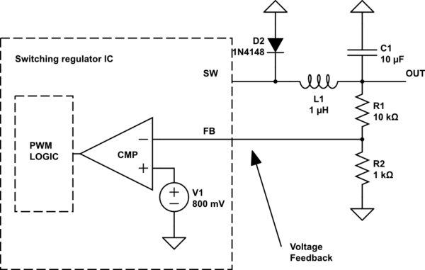
Most today used switching regulator ICs that I've seen have some kind of feedback voltage pins. I think I've pretty understood the way it works:
A resistor divider from output to ground is created to fed back some portion of the output voltage to the feedback amplifier that will generate a voltage for the PWM generator logic.

simulate this circuit – Schematic created using CircuitLab
The voltage will be compared to some internal reference voltage, 800mV in this example. If the feedback voltage is higher than that reference the PWM generator will be turned off, otherwise the duty cycle will be adjusted accordingly.
My goals are:
- Trying to build a power supply with the ability to electronically control the output voltage.
- Trying to understand whats going on
My question is, what is the best way not to use this static resistor divider but to use some proportional voltage? My Idea was to generate a reference voltage (my desired regulator output voltage) with help of a micro controller and an DAC. If I know the required proportion of R1 to R2 to generate a specific voltage I can derive a division factor like:
\$V_{FB} = \frac{V_{O}}{N}\$
The division factor N is a function of output voltage in most cases as I found out. However I have no idea to build that kind of circuit. Should I use logarithmic opamps for that kind of mathematical division or is there a better solution which I have not even considered? May be there is a much simpler solution?
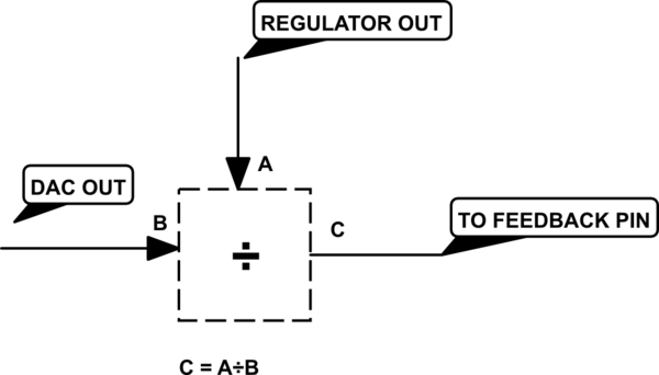
Edit: My basic idea

This kind of operation would be possible either with two expensive logarithmic op-amps or by very expensive special purpose circuits. Because it use analog voltages without taking a detour over ADC/DAC, latency would be low enough. But as I said I'm not sure if there are better ways.
