0
\$\begingroup\$

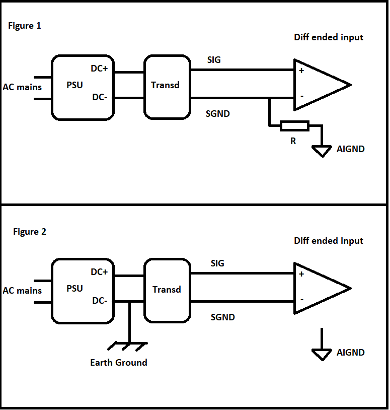
Regarding this paper, I first tried to wire single-ended floating sources to a diff ended data acquisition board. But because of some power supply related issues and not wanting to make another interface for bias resistors I want to try another configuration by converting floating sources(0 10V DC outputting transducers like humidity, temperature ect) to grounded sources. So basically my sources are single-ended(not bipolar) and the DAQ board is diff ended.

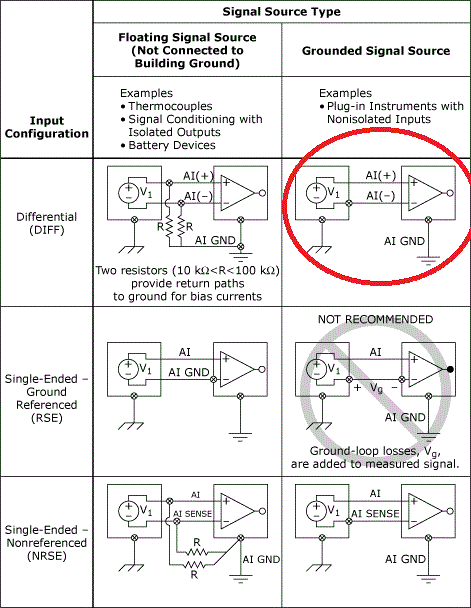
To make it clear what I mean here are the general configurations from the paper:

enter image description here

In above table, I was using the the one on the top left with bias resistor and now I want to try the encircled one in red.

My questions are:

Here I made a more practical drawing:

enter image description here

As you see above the Figure 1 represents my current wiring scheme. And in that there is no earth ground involved. But still I'm having issues. And now I want to change this to "grounded sources to diff ended" scheme like the one encircled in red.

Regarding the red encircled configuration from the original paper:

1-) Can I do this floating to grounded scheme by using earth? Is my Figure 2 correct?

2-) No extra wire needed to be wired to AIGND?

3-) I wired the DC- to earth ground, but is this correct? I'm not sure whether DC- or SGND must be wired to earth ground. Because sometimes I observed wiring DC- to the earth reduces 50Hz interference.

\$\endgroup\$

1 Answer 1

0
\$\begingroup\$

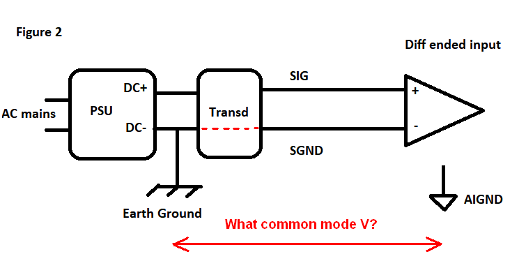
You have to ask yourself what common mode voltage might appear between "earth" and AIGND: -

enter image description here

Then you have to check whether your DAQ differential inputs can handle this voltage both safely (without destruction) and without unacceptable performance degredation.

I wired the DC- to earth ground, but is this correct? I'm not sure whether DC- or SGND must be wired to earth ground.

If both are internally connected inside the transducer (as per the dotted red line above) then it won't matter.

\$\endgroup\$
2
  • \$\begingroup\$ Thanks but I have some lack of knowledge when I look at these figures. 1-) For example in your drawing AIGND is not connected to earth ground right? 2-) Can I measure that common-mode voltage by a multimeter AC setting? 3-) If the commonmode voltage is high what can be the workaround for this config? \$\endgroup\$
    – floppy380
    Commented Mar 13, 2018 at 11:16
  • \$\begingroup\$ I don't know what AIGND connects to - I would assume it connects through to "earth" at some point but this is down to you. Measuring it on a good day might convince you it will work but, on a bad day it could be several volts peak to peak. You need to estimate/calculate what it might be worst case. Again, I can't help you with this because I know nothing about your plant/factory/installation set-up. If CM voltage is high then you have to use isolation methods. Measuring with a meter doesn't tell you anything about any RF/high frequency CM noise unless you have a suitable meter. \$\endgroup\$
    – Andy aka
    Commented Mar 13, 2018 at 11:25

Your Answer

By clicking “Post Your Answer”, you agree to our terms of service and acknowledge you have read our privacy policy.

Not the answer you're looking for? Browse other questions tagged or ask your own question.