2
\$\begingroup\$

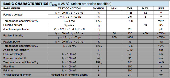
I'm trying to build my own IR-led light with multiple LEDs. I've bought a TSAL6100 IR led but I'm not sure how to interpret the data sheet, I can't find any reference in internet. Can anybody tell me where I can find the informations or interpret these parameters and tell me how to use them? enter image description here

enter image description here

I'm an "hobbist"!

I would like to know the difference between basic characteristics and absolute maximum ratings, which one of these contains the information for the normal usage?

EDIT: What does it means TYP column? Typical usage or is a mean in case of voltage drops? Why I_F in Absolute maximum rating is 100 mA but in basic characteristics is 1 A with pulsed? Why even for 100 mA the t_p is 20 ms so I should use this led only in pulsed?

\$\endgroup\$
3
  • \$\begingroup\$ Any particular one of those that is puzzling to you? There's 30 or 40 of them. You make gears for a living? \$\endgroup\$ Commented Mar 24, 2014 at 16:38
  • \$\begingroup\$ @SpehroPefhany in fact I don't know which are the main parameters to look I imagine that knowing the maximum Amp and V could be useful. \$\endgroup\$
    – G M
    Commented Mar 24, 2014 at 18:02
  • \$\begingroup\$ P.S. I don't care about spectral and lighting parameters. \$\endgroup\$
    – G M
    Commented Mar 25, 2014 at 8:55

3 Answers 3

4
\$\begingroup\$

Okay, with your comment on Vf and current, let's start with that. I'm going to assume it's a CW (not pulsed) light you're going to make.

A good place to start is the current where the LED is tested, 100mA in this case, since that's where the manufacturer thinks it would be useful to specify parameters.

Typically, the LED drops 1.35V at 100mA. That means it dissipates 135mW (V * I). Note that they specify the voltage drop with a 20msec pulse. That means that the junction temperature is almost the same as the ambient temperature. As the LED heats up, the voltage goes down by 1.8mV for every degree C (2nd parameter), so it will dissipate a bit less heat as it warms up, but then the 1.35V is just the nominal, so let's use that as the voltage at the maximum temperature to allow a bit of safety margin. If you want to be really cautious, you might use the maximum voltage (1.6V, leading to 160mW dissipation).

The absolute maximum junction temperature is 100°C (2nd set of parameters). For good life, we want to stay well away from that. Let's arbitrarily say 80°C Tj is acceptable.

Thermal resistance is 230K/W (same as °C/W), so at 135mW it will heat up by 31°C soldered to a PCB with 7mm leads. At 100mA, the air around the PCB could be as hot as 49°C before heating the junction above 80°C. If there are many LEDs mounted closely together, that may not be possible if the air outside is warm, but you can see that you certainly don't want any other stuff nearby contributing heat. If it's getting too hot, you need to reduce the current, perhaps to 80mA or 70mA.

The forward voltage is typically 1.35V. At 80°C it would be more like 1.25V, but it could be a few hundred mV more or less, according to the datasheet- worst case is 1.60V minus 0.1V for temperature coefficient, so 1.50V, which would cause a few more degrees heating.

Note that the wavelength shifts a little further into the infrared as it heats (that's normal).

Normally if you're using an array you'd want to use a series-parallel arrangement. Say your supply is 12V and you want to power 14 LEDs, you could use two series strings of 7 LEDs with two constant-current sources of 100mA that work down to 0.5V or so. That would draw 200mA at 12V for all 14 LEDs.

Edit: Something like this where the op-amp, BJT and resistor represents part of a 100mA current sink.
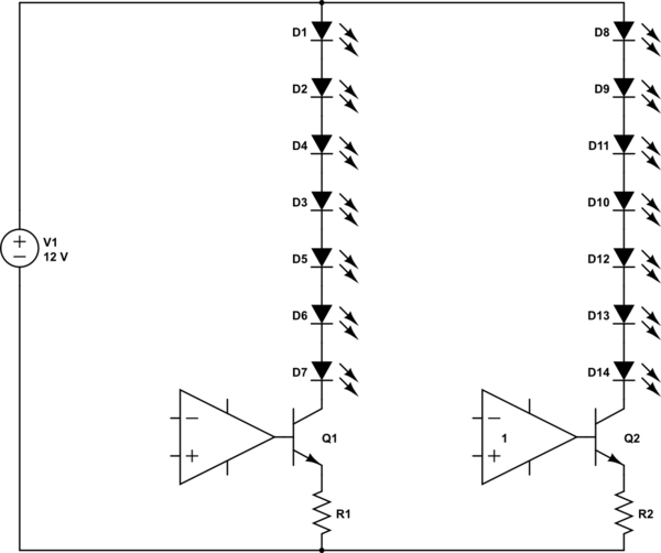
schematic

simulate this circuit – Schematic created using CircuitLab
\$\endgroup\$
2
  • \$\begingroup\$ +1 thanks for the great answer! So if I have 24 LEDs I need 24 Volt maybe to much... I've not understand the last part do you suggest to connect 7 leds in series and draw 200mA through them? \$\endgroup\$
    – G M
    Commented Mar 24, 2014 at 18:54
  • 1
    \$\begingroup\$ See edit above for the rough outline. The design of the current sink or picking resistors has been covered elsewhere here. \$\endgroup\$ Commented Mar 24, 2014 at 19:54
3
\$\begingroup\$

I've never used this device before but I'd be interested first in the eye-safety risk assessment from Vishay if I were building it. It's quite a high power device and at the point on the spectrum that it emits the lens in the eye is capable of focussing the energy onto the retina.

I mention "building it" because this might be the situation that can cause maximum damage because of incorrect current limiting and then closely visually inspecting the circuit board with power on. That might cause a problem so do your homework and double check and, if necessary proceed with caution.

From your specification, it can emit an optical power of 400 mW/sr. The limit statements below indicate that 4 watts / sr are OK at 0.2 metres BUT I would say that if you are wearing eye magnifiers and looking close at the device (foolishly of course) you might do some damage.

This is just a cursory quick check so re-check and double check.

enter image description here

\$\endgroup\$
2
  • \$\begingroup\$ Thanks for the warning! The danger is not the IR light it self (an 50 W tungsten light bulb emit much more IR radiation) but the fact that you don't see it when I worked with NIR laser at university I've got the same problem so you risk to look straight into the source for a long time without feel it. Thanks for remind me that! \$\endgroup\$
    – G M
    Commented Mar 24, 2014 at 20:20
  • 1
    \$\begingroup\$ $150-$200 for a good pair of laser-rated goggles is a good investment if you're going to be working with high intensity sources. I have an OD7 pair for IR (10^-7 transmittance), which still lets a reasonable amount of room light through. \$\endgroup\$ Commented Mar 24, 2014 at 20:43
3
\$\begingroup\$

Most important things to take notice of:

  • [Maximum] Forward current the current you can continously without pause feed to the diode without killing it - 100mA
  • Peak forward current the amount of current the diode can handle when it's being lit with pulses, not a steady current, pay attention to the timing details! - 200mA for a square wave with a period of 100/0.5=200uS and pulse width of 100uS (50% duty cycle at 5000Hz)
  • Forward voltage the voltage you should use when calulating the limiting resistor for current (depends on the amount of current that flows through the diode) 1.35-1.6V for normal operation
  • [Maximum] Reverse voltage If you apply a reverse voltage greater than this to the diode, it very well might end it's working life (pay attention to the power supply and LED polarity) - 5V
  • [Maximum] Power dissipation $$Power\,dissipated = Current\,through\,diode \times Voltage\,over\,diode$$ If you go over the rated power dissipation the diode will heat up and eventually melt so calculate accordingly. You can power the diode with square pulses, and do $$Average\,power\,dissipated = Power\,dissipated \times duty\,cycle$$ to estimate the permissible currents for PWM operation.

The rest don't seem critical to regular use or are quite self-explanatory, but if anything's unclear, comment and ask more.

\$\endgroup\$
1
  • \$\begingroup\$ Thanks Ricardo, I didn't know about the formula formatting! \$\endgroup\$
    – Linards
    Commented Mar 24, 2014 at 21:36

Your Answer

By clicking “Post Your Answer”, you agree to our terms of service and acknowledge you have read our privacy policy.

Not the answer you're looking for? Browse other questions tagged or ask your own question.