4
\$\begingroup\$

Please note: this question refers to the electrical engineering part of the design, optical configuration is not request (advices are however welcome)

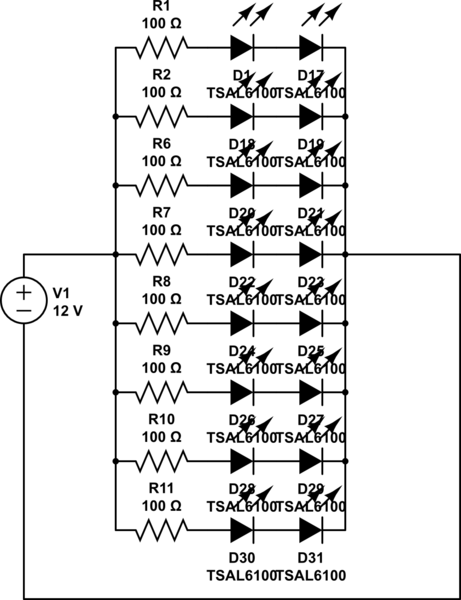
I'm trying to design a LEDs lamp with an homogeneous output for a radiometric experiment (so I don't care about energy consumption but I would like a safe prototype, so I prefer a low voltage, that works decently even if is not the best way to do it). So far I've seen different approach: in this video seems that for build an LEDs matrix I should use a resistor for every LED. However I think that parallel arrangement does not produce an homogeneous output, (i think some LED will be brighter...) so I think Spehro answer to my first question could be the best alternative, however I don't understand how to design the last part of his circuit (op-amp, BJT... ) furthermore I think that a long series could have the same effect due to the non-ohmic nature of LEDs (Am I wrong?). So I've tried a different approach but I don't know if it is right. Here is the schematics:

schematic

simulate this circuit – Schematic created using CircuitLab Assuming that LED's If=100mA and Vf=1.35 V and I have a 12 V source, if I'm not wrong I need: $$ R=\frac{12V~-(1.35V \times 2)}{0.1A}=93\Omega$$ so I can use a 100 Ohm resistor (I don't know why I can't run the simulation, but power consumption should be under 4 W).

My specific needs:

  1. lamp from 12 to 22 LEDs
  2. not necessarily high output so LEDs can be light even with lower current e.g. 70 mA
  3. not high voltage I want a "safe" prototype
  4. power consumption is not a problem, so can be inefficient, I want only homogeneous output and something that don't auto-ignite or burn thing that get in touch (e.g. my hands).
  5. The lamp will not turn on for long period of time, typical working session could be about 5-30 min.

Which is the best way to have the same brightness from all the LEDs without use a dangerous voltage? And just for curiosity Which is the best way at all, no matter voltage or power consumption?

\$\endgroup\$
8
  • \$\begingroup\$ How many LEDs? How close must the light output of each LED be to the nominal? The best method can be very different depending on these parameters. \$\endgroup\$ Commented Apr 7, 2014 at 20:18
  • \$\begingroup\$ @OlinLathrop I've edited the question, specification in the linked question. For nominal you mean the current passing through the LED? \$\endgroup\$
    – G M
    Commented Apr 7, 2014 at 20:27
  • \$\begingroup\$ That answers one of my two questions. Also, I understand that power consumption may not be a issue, but are you prepared to deal with the heat generated by a inefficient design? \$\endgroup\$ Commented Apr 7, 2014 at 20:31
  • \$\begingroup\$ @OlinLathrop From my last calculation power consumption was under 4 W...Should I worry about it? \$\endgroup\$
    – G M
    Commented Apr 7, 2014 at 20:49
  • \$\begingroup\$ You still haven't answered one of my original questions. \$\endgroup\$ Commented Apr 7, 2014 at 21:17

11 Answers 11

7
+50
\$\begingroup\$

There are two things to consider in trying to match the light output of multiple LEDs

  1. Controlling the current thru each LED.

  2. Compensating for light output variances between LEDs even when driven with the same current.

The first is not that hard to guarantee electrically. The brute force way to ensure the same current thru all LEDs is to put them in series. That will require the highest drive voltage, but the currents will be equal.

It is not clear if you also care about variations in light intensity between LEDs driven at the same current. If so, it gets trickier because these variations by their very nature are device by device and can not be known other than by explicit testing.

The first order answer is to simply string the LEDs in series with a resistor, using a high enough voltage source.

The second order answer is to do the same thing but specifically buy matched LEDs, or buy a large quantity and find matched ones yourself. LED manufacturers routinely measure the light output of individual LEDs and "bin" them according to brightness. Buying a set of LEDs binned to the same brightness is more tricky, and may require working with your distributor or directly with the LED manufacturer if the volumes are high enough.

The third order answer is to trim the light output of each LED separately. To do this you will need some means to measure the light from individual LEDs, and to adjust the current thru individual LEDs. This is obviously the most complicated approach and requires the most parts, but produces the best match.

There are various ways to trim the light output of each LED. Which one is appropriate depends a lot on parameters you haven't given us, like the number of LEDs and and how close "close" is. Also, how automated must the trimming process be? Is this something a technician can do laboriously once, or must it be easy to do by unskilled people at unforseen times?

Added:

We finally have a spec that says the light output of each LED can vary up to 5% of nominal. That is quite tight. A human wouldn't be able to see a 5% difference in intensity even when the two LEDs are viewed side by side. This is therefore tighter than I think you can get by buying binned LEDs. I may be wrong, so check with some distributors or manufacturers. However, I'll proceed here assuming you can't buy LEDs this close to each other in brightness, and therefore individual trimming is required.

You didn't say what kind of LED you will be using or a link to a datasheet, so I'll do this example for ordinary green LEDs with a maximum sustained current of 20 mA and a forward drop of 2.1 V. The same topology will work for other currents and forward drops, but of course will require different values in the circuit.

Here is a circuit per LED that should allow you to get what you want:
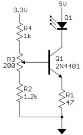
The "3.3V" supply is intended to be well regulated and is used as a voltage reference. The 5V supply does not need to be very accurate, and significant ripple can even be tolerated. The easy way to get both these is to go out and buy a 5 V supply, then use a linear regulator to make the 3.3 V from it.

This circuit works by using the bipolar transistor as a current sink. It is exploiting the fact that the collector current varies little as a function of collector voltage as long as that collector voltage is above some minimum, like 1 volt or so. The base voltage is adjusted by the R4-R3-R2 divider chain to keep about 1 volt accross R1, which keeps the LED current close to 20 mA.

With 1 V on R1, the collector should be at least 2 V to keep the transistor regulating the current nicely. In this example the LED drops 2.1 V, so the minimum the "5V" supply can be is 4.1 V. Higher voltages will work too, but cause increased dissipation. Any off the shelf regulated 5 V supply should work fine here. Since you want to support up to 22 LEDs and each will draw 20 mA, the supply must be able to source 440 mA for the LEDs alone. Leaving room for another 2 mA per LED for the control circuitry, the current requirement is close to 1/2 A. A 5 V 1 A supply can therefore easily do this. Fortunately those are cheap and available.

To trim this, turn down all the R3 pots to their minimum end (wiper is effectively between R3 and R2), then apply power. Use a voltmeter to adjust each R3 so that the corresponding R1 has 940 mV accross it. This step guarantees that none of the LEDs are overdriven, but all are close to their upper limit. Now go around and measure the light output of each LED to find the dimmest one. Then adjust R3 of all the remaining LEDs to match that light output.

One way to measure relative light output would be with a CdS photoresistor in a Wheatstone bridge driving a voltmeter. If you put a small pot in the bridge, you can trim it for null output from the dimmest LED, then adjust the others to get that null output. In any case, there are various ways to measure light, so getting into that more is a side issue to this question.
\$\endgroup\$
10
  • \$\begingroup\$ +1 thanks for the answer, the lamp should be similar to that I've design in the question (we can say from 12 up to 22 LEDs). I want the best homogeneous light output no matter how much time it will cost me. So you say series other users told me to use multiple resistor, I'm confused... My half way is valid? \$\endgroup\$
    – G M
    Commented Apr 7, 2014 at 20:36
  • \$\begingroup\$ @GM: AGAIN, how close is close? Is getting matched LEDs good enough, or do you need each to be within 1% light output, for example. That makes a large difference. You need to answer ALL questions I ask. I ask them for a reason, whether you understand that reason or not. I'm trying to help, but this is getting tedius with you not answering direct questions. \$\endgroup\$ Commented Apr 7, 2014 at 21:20
  • \$\begingroup\$ Thanks for the help, I trust you and I gladly answer to your questions but I have to understand the question before I can answer it: how close is close?I'm sorry, I thought you were talking about the number of LEDs. I would like to know the most homogeneous at all, however alternatives up to 5 % are welcome `how automated must the trimming process be? Is this something a technician can do laboriously once, or must it be easy to do by unskilled people at unforseen times?It's a prototype I can spend all the time and efforts that it needs. Thanks for the help! \$\endgroup\$
    – G M
    Commented Apr 8, 2014 at 8:05
  • 2
    \$\begingroup\$ Kind of reinforcing Olin's line of thinking here: There is no "most something or other" in engineering... only "most something, given limited time, money, measuring equipment etc etc". One of the "etc" here is there's no point perfecting the uniformity of LED array beyond irregularities in the rest of the system, eg: the effect of a grid rather than plane of light, non-uniform position of LED chip vs its lens (if any), diffuser surface, stronger illumination on-axis vs off-axis, other sources of illumination etc. If you can assess those, you can figure how much refinement really matters. \$\endgroup\$
    – gwideman
    Commented Apr 8, 2014 at 11:09
  • 2
    \$\begingroup\$ You'd spend all your time matching in the 25C lab then you change temperature and intensity changes. For best precision, you would buy all the LEDs from the same wafer ($$) (unless tuned).If you have a bunch of LEDs in series how can you trim them individually? Maybe it'd be cheaper to have some kind of lense that could diffuse the light or something or tune it that way. To Olin's point, if you don't understand your accuracy requirement you're just going to be wasting your money. Perfect is asymptotic and approaches infinite cost.. also PWM might be easier to tune in a lab and in application.. \$\endgroup\$ Commented Apr 8, 2014 at 13:46
3
\$\begingroup\$

Couple of comments about the optical portion of your project:

Both the electrical and optical portion of the project are important but you won't be able to achieve a homogenized optical output even with perfect drive electronics unless you worry about the optical portion of the design which in turn may constrain how you plan to build/drive the device.

Each LED will emit an ugly intensity pattern that will be hard to create a homogenized beam out of. The way to correct for this is with a homogenizer. There are many different types of homogenizers available but how useful they are depends on your requirements and the application.

Magic Tape Cheap. Works very well for a lot of applications including LEDs.Seriously this stuff works great.

Ground Glass Diffuser Also Cheap. Highly Transmissive. Will give more of a Gaussian output shape than lambertian.

Integrating Sphere: Expensive. Great for creating lambertian sources and for detection. Multiple reflections inside a sphere coated with a highly reflective white coating generate a very homogenized beam.

Holographic Diffusers Similar to glass diffusers but with custom output shapes and higher transmittance. More expensive than glass cheaper than an integrating sphere.

\$\endgroup\$
1
  • \$\begingroup\$ thanks, unfortunately I know the price of Thorlabs! I will try to see if Magic Tape works! P.S. first two links don't works to me... \$\endgroup\$
    – G M
    Commented Apr 7, 2014 at 20:11
2
\$\begingroup\$

Which is the best way to have the same brightness from all the LEDs?

There are three options: -

  1. Accept the manufacturing differences in light intensity between LEDs in a batch you buy
  2. Use a light meter and calibrate/test each one on a precision current source and be prepared to throw away 50% that aren't "good enough"
  3. Put variable resistors in series with each one and wire in parallel. Adjust the resistor to match the light output to the rest.

End of.

\$\endgroup\$
5
  • \$\begingroup\$ thanks for the answer, so put a resistor for every led is better rather than use a resistor for a couple of LEDs like in my schematics? \$\endgroup\$
    – G M
    Commented Apr 5, 2014 at 20:27
  • \$\begingroup\$ The trouble is with doing it this way is that all the LEDs/resistors are in parallel and this might mean a lot of wasted voltage and power dissipation in each resistor. With them all in series, at least they share a common current source with one current limiting resistor. I suppose you could equalize bright ones with a 10k rheostat across the overly bright LEDs and take it from there. You might get a better result doing it this way. \$\endgroup\$
    – Andy aka
    Commented Apr 5, 2014 at 20:43
  • \$\begingroup\$ Maybe also a bit of this and a bit of that - match up what you can and then they can all be dimmed/brightened with a single resistor - for the rest you match up what you can and mess around with series/parallel resistors. \$\endgroup\$
    – Andy aka
    Commented Apr 5, 2014 at 20:44
  • \$\begingroup\$ thanks for the clarification, it was my intention to put a rheostat however only one so wont be useful for homogenous lighting; efficiency is not a problem! I think a will do some test... \$\endgroup\$
    – G M
    Commented Apr 5, 2014 at 20:52
  • \$\begingroup\$ I was going to post an answer, but your third option beat me to it. If this a setup for an experiment and we aren't concerned about manufacturablility, a variable resistor for each LED is the best approach to get the same light intensity. This compensates for all loses. Make sure you get a proper light meter and have a very well controlled method for measuring the lumens from you LEDs. \$\endgroup\$ Commented Apr 8, 2014 at 14:53
2
\$\begingroup\$

Which is the best way to have the same brightness from all the LEDs without use a dangerous voltage?

Best depends on how complex you get and how matched you need. A simple method for a one off project, is taking a bunch of leds, say 4 parallel strings of 4 in series with an appropriate resistor on each. Light them up, then move them around by hand to match each string. Once you have done the best, you start adjusting the resistors until all 4 strings match. A small trimpot would be useful. You might need more than just 16 leds, if some are completely unmatchable.

I've done this with 7 individual leds for a larson scanner. Some of my red leds just dont have the same color tone.

And just for curiosity Which is the best way at all, no matter voltage or power consumption?

Again, depends on your needs. You can use a digital led control IC that has current matching as well as individual channel spot correction.

\$\endgroup\$
2
\$\begingroup\$

You should worry more about optical part of your light source device.

Your circuit will be pretty homogeneous.

You can use resistors with 1% tolerance if you want more precision

or

buy more 5% resitors measure all of them and only pick resistors closest to 100 ohm.

\$\endgroup\$
2
\$\begingroup\$

Assuming your resistors are similar and your LEDs are well matched, the circuit that you have show will give equal brightness.

However, because there are manufacturing differences between both the LEDs and the resistors, it won't quite be equal. You could do some voltage matching between LEDs to be the same. Basically, put an appropriate resistor in line with the LED, and measure the actual voltage drop. Put the LEDs in series so that the total voltage drop between each set of LEDs is as close as possible.

However, it's pretty simple to drive it with line voltage. If you used 40 LEDs, that would drop 108 volts, and to drop the remaining 12 volts would take a single 120 ohm resistor. That would dissipate 1.2 Watts. I'd suggest using three 39 ohm 1/2 watt resistors in series.

This gives you 100 mA through every LED.

I would recommend a full-wave rectifier as well, so that you have reduced flicker.

\$\endgroup\$
1
  • \$\begingroup\$ thanks for the answer so which is the best way to do it whit a low voltage (I think I will use 12 volts)? \$\endgroup\$
    – G M
    Commented Apr 3, 2014 at 9:21
2
\$\begingroup\$

It may be possible to use a multichannel driver with dot correction such as the TLC5940 and adjust the dot correction of each channel individually until each LED appears the same. The '5940 can sink up to 17V, and 120mA when VCC is above 3.6V.

\$\endgroup\$
1
\$\begingroup\$

First, you could ask the LED manufacturer to provide to you the same bin.

I don't know about your particular LED, but often, when the LED model is meant for lighting, the manufacturer can provide LED that have the same electric and optical parameters. To be simple: The manufacturer sorts the LED. You can ask to have all your LED from the same "bin". They will have a much reduced differences between them. Then, using a precision resistor in series with them, you may achieve very similar brightness. If, and only if, they are thermally coupled. They have to be all at the same temperature. And I am sure that your setup is not optimized to ensure that the thermal dissipation is identical for all the LEDs.

The second solution would be to add a laser trimmed resistor in series, then ask the manufacturer of your module to trim it until the LED have reached a given brightness. But this is not sufficient to guarantee the same illumination between the two LED that are place on the same branch. Only sorting them and ensuring a thermal coupling can make it. At least if it is required to stay with your proposed topology...

\$\endgroup\$
1
\$\begingroup\$

None of the solutions addressed the variation of luminous intensity of each 20 deg beamwidth LED. Since LED assembly is either square or hexagonal, it does not matter how well matched your LEDs are when they vary 50% at +/-10 deg. Imagine the dimple pattern with overlap . You are trying put a round cone of light into a square pattern. It wont work.

Your only solution is to use a single 10W lambertian array LED and add a large diffuser / focus lens from Edmund Scientific to give a large straight light beam thru your target and crop the outer area below which you is out of tolerance. ( insufficient brightness )

Alternatively use a large array of extra light to account for transmission losses and diffuser film to make a plane wave of light, like ceiling tile for FL tubes. That works but very lossy.

\$\endgroup\$
0
\$\begingroup\$

All circuit elements which are in parallel will experience the same potential difference across them. Now start with the LEDs, the LEDS which I am using currently (in a personal project) http://uk.rs-online.com/web/p/visible-leds/7134888/ have a "forward voltage" of around 4V and a absolute maximum current of 80mA per LED. I have added resistors in so that when using the R G or B channel, or some combination of them, the resistance along each path to ground (each parallel branch) is equal. You must consider that when you have multiple elements in parallel (or multiple parallel paths to ground) that the current will take the path of least resistance. If you update your question with the datasheet of the LED you want to use, and say how many of them you need then I can suggest a design. As Eric Gunnerson says some sort of rectifier/smoother is a good idea.

\$\endgroup\$
2
  • \$\begingroup\$ Thanks for the answer, the specification are in the other linked question, but the main are however already in the question, I would like to make a lamp similar to that I've design in figure (from 12 to 25 LEDs) not high voltage. Thanks for the help! \$\endgroup\$
    – G M
    Commented Apr 3, 2014 at 10:27
  • \$\begingroup\$ Sorry I've see now that the link was wrong try to look now, there are all the specifications.. \$\endgroup\$
    – G M
    Commented Apr 5, 2014 at 20:30
0
\$\begingroup\$

I'm certainly no expert but I think this other answer about efficiency using linear and switched mode circuitry is closely related to what you are looking for.

How can I efficiently drive an LED?

I understand that in your question you explicitly don't care about efficiency per se. But the switched mode circuitry gives a consistent output regardless of variations on input.

\$\endgroup\$

Your Answer

By clicking “Post Your Answer”, you agree to our terms of service and acknowledge you have read our privacy policy.

Not the answer you're looking for? Browse other questions tagged or ask your own question.