19
\$\begingroup\$

I'm marginally familiar with the way that an AC transformer works. After viewing this question:

Why don't all motors burn up instantly?

It got me thinking about the same thing with AC transformers.

The primary coil should provide very little resistance and thus allow a lot of current to flow. I'm guessing that the resistance comes from the fluctuating magnetic field. Is this correct? If so, I'm assuming that the current increases when a load is placed on the secondary coil because the magnetic field doesn't collapse into the primary coil but is used by the secondary coil instead?

Also, does this mean that if a DC current was placed on a transformer that it would cause trouble? (i.e. very high current)

I'm sure I'm not saying this correctly, so I'm hoping someone can set me straight.

To sum up my question, what is the behavior of a transformer's primary coil (in terms of current flow) when no load is placed on the secondary coil, and what changes when a load is placed on the secondary coil?

\$\endgroup\$
6
  • 2
    \$\begingroup\$ "AC" transformer is redundant. All transformers inherently work on AC. \$\endgroup\$ Commented Mar 24, 2014 at 21:58
  • \$\begingroup\$ @OlinLathrop At room temperature, anyway. \$\endgroup\$ Commented Mar 24, 2014 at 22:44
  • 3
    \$\begingroup\$ @OlinLathrop Well, "DC current" is literally redundant. \$\endgroup\$
    – Samuel
    Commented Mar 25, 2014 at 3:46
  • 2
    \$\begingroup\$ LCD Display, PIN Number... I like this game! \$\endgroup\$
    – John U
    Commented Mar 25, 2014 at 10:15
  • 1
    \$\begingroup\$ Beautiful question. Just what I was wondering. Thanks for asking. You described it well \$\endgroup\$ Commented Mar 15, 2023 at 22:18

4 Answers 4

24
\$\begingroup\$

Andy gave you the classic academic answer to your questions. Everything he stated is accurate, but I doubt as a beginner you will understand most of it. So, let me take a try at a simple explanation.

The primary of a transformer is a coil wound around an iron core which can take one of several shapes. This primary winding has a very low resistance. ( Measure the resistance of a typical power transformer used in electronic bench equipment with a DMM and you will find it is just a few Ohms.) Connect a DC voltage source to this, the result is quite predictable. The voltage source will deliver as large a current as it is capable of to the primary winding and the transformer will get very hot and probably go up in smoke. That, or your DC supply will blow a fuse, burn up itself, or go into current-limit mode if it so equipped. Incidentally, while this high current is flowing, the primary winding is actually producing a uni-directional magnetic field in the transformer core.

Now, measure the inductance of the secondary with an LRC meter. (That's a DMM-like device which measures only inductance, resistance and capacitance - "LRC".) For a 60 Hz power transformer you will likely read a few Henries of inductance across its primary leads.

Next, apply that "L" value to the formula \$X_L = 2 \pi f L \$ to calaculate the "inductive reactance" ( "\$X_L\$" ) of the primary winding where "f" is the AC Main frequency of 60 Hz for the USA. The answer, \$X_L\$, is in units of Ohms just like DC resistance, but in this case these are "AC Ohms", aka "impedance".

Next, apply this value of \$X_L\$ to "Ohm's Law" just like you would with a resistor connected to a DC source. \$I = \frac{V}{X_L}\$. In the usual USA case we have 120 volts RMS as V. You will now see that the current "I" is a quite reasonable value. Likely a few hundred milliamps ("RMS" also). That's why you can apply 120 volts to the unloaded transformer and it will run for a century without a problem. This few hundred milliamp primary current, called the "excitation current" produces heat in the transformer primary coil, but the mechanical bulk of the transformer can handle this amount of heat by design virtually forever. Nonetheless, as described above, it wouldn't take a 5 VDC power supply but a few minutes to burn up this same transformer if that DC supply was capable of supplying a large enough current to successfully drive the low-R DC coil. That's the "miracle" of inductive reactance! It's the self-created alternating magnetic field produced by the AC current itself in the transformer core which limits the current when driven from an AC voltage source.

That's for the unloaded transformer. Now, connect an appropriate resistive load to the secondary. The excitation current described above will continue to flow at more-or-less the same magnitude. But now and additional current will flow in the primary. This is called the "reflected current" - the current which is "caused" by the secondary resistive load drawing current from the transformer's secondary. The magnitude of this reflected current is determined by the turns ratio of the power transformer. The simplest way to determine the reflected current is to use the "VA" (volts-amps) method. Multiply the tranformer's secondary voltage by the current in amps being drawn by the resistive load attached to the secondary. (This is essentially "Watts" - volts times amps. ) The "VA Method" says that the VA of the secondary must equal the incremental VA of the primary. ("Incremental" in this case means "in addition to the excitation current".) So, if you have a typcial AC power transformer with a 120 VRMS primary and a 6 VRMS secondary and you attach a 6 Ohm resistor to the secondary, that 6 Ohm load will draw 1.0 Amp RMS from the secondary. So, the secondary VA = 6 x 1 = 6. This secondary VA must numerically equal the primary VA, where the voltage is 120 VRMS.
Primary VA = Secondary VA = 6 = 120 x I.
I = 6/120 or only 50 milli-Amps RMS.

You can verify most of this using a simple DMM to measure the currents in the primary and secondary under no-load and load conditions. Try it yourself, but be careful on the primary because that 120 VRMS is near-lethal. However, you will NOT be able to directly observe the "incremental" current in the primary caused by adding the load to the secondary. Why? That answer is not so simple! The excitation current and the reflected current are 90 degrees out-of-phase. They "add up", but they add up according to vector math, and that's another discussion altogether.

Unfortunately, Andy's beautifully expressed answer above will be barely appreciated unless the reader understands vector math as it is applied to AC circuits. I hope my answer, and your verification experiments, will give you a gut-level numerical understanding of the how a power transformer "works".

\$\endgroup\$
6
  • 1
    \$\begingroup\$ "simple explanation" = 53 lines of words compared to my 22 lines and two pictures LOL \$\endgroup\$
    – Andy aka
    Commented Mar 25, 2014 at 16:08
  • \$\begingroup\$ I'm getting the sense that there is no "simple" answer here \$\endgroup\$
    – Matt Ruwe
    Commented Mar 25, 2014 at 18:46
  • 1
    \$\begingroup\$ Matt, There are "simple" answers to many questions, be they complex or simple questions. It's just that simple answers are not always complete answers. Also, simple answers are often merely analogies or metaphors. These often offer up specious explanations in place of true explanations. "Specious" means "enticingly plausible, but untrue". There's a lot of that going around lately, particularly on the nightly news. \$\endgroup\$
    – FiddyOhm
    Commented Mar 30, 2014 at 13:57
  • \$\begingroup\$ Where you wrote "measure the inductance of the secondary", did you mean the primary? \$\endgroup\$
    – Kevin Reid
    Commented Apr 1, 2016 at 19:33
  • \$\begingroup\$ @Kevin Reid I also stumbled there... I think it's a typo. \$\endgroup\$
    – yippy_yay
    Commented Mar 7, 2019 at 18:42
14
\$\begingroup\$

I'm assuming that the current increases when a load is placed on the secondary coil because the magnetic field doesn't collapse into the primary coil but is used by the secondary coil instead?

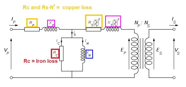
It sounds right but it isn't. Generally speaking, for a reasonably efficient transformer, the magnetization of the core is constant under any secondary load conditions. The trouble is, how do I explain that without convincing you that the transformer equivalent circuit (below) is not wrong: -

enter image description here

Things to note: -

  • Xm is 99.9% the primary inductance of the transformer
  • Xp (primary leakage inductance) makes up the final 0.1% of the primary inductance
  • Xs and Rs are secondary leakage inductance and winding resistance referred to the primary by action of the turns ratio squared.
  • The thing that looks like a transformer (to the right) shouldn't be regarded as such - it is a perfect power converter and generates no magnetism at all - it is a device to help the maths and I wish the boffins who draw these pictures would just show it like a black box!!

As you may be able to see, even under heavy load conditions, the volt-drop from Rp and Xp is small compared to an input AC voltage and this means that the voltage across Xm is fairly constant. Note that Xm is the only component that produces magnetism in the core. Not convinced eh? I wouldn't blame you.

Here's another way of looking at it

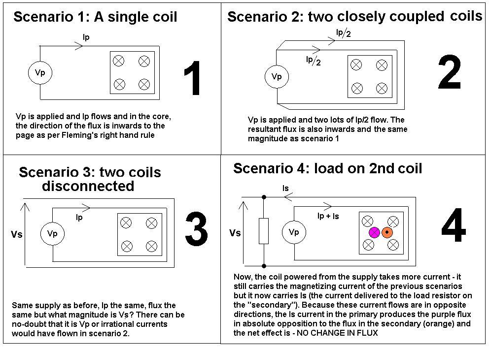
The series of 4 pictures below attempt to demonstrate that the flux contributions from load currents in both primary and secondary are equal and opposite and therefore the flux cancels. It shows a simple 1:1 transformer but applies equally to different turns ratios because flux is proportional to ampere-turns and not amps. Look at each picture numerically in turn: -

enter image description here

\$\endgroup\$
5
  • \$\begingroup\$ Perhaps instead of saying the thing on the right "isn't a transformer", you should say that it is a magical ideal transformer that works at all frequencies from DC to daylight; a typical real transformer may be modeled as a magical ideal transformer with all the stuff added to the left. Alternatively, one could imagine a massless ideal DC motor with two commutators and two sets of windings; the motor would turn however it needed to maintain the same relationship on its two "power connections" as would exist on an ideal transformer. \$\endgroup\$
    – supercat
    Commented Mar 31, 2014 at 16:50
  • \$\begingroup\$ The main difference between the ideal transformer and the ideal motor-generator would be that in the ideal transformer, nothing would have to actually move. I think the analogy may be helpful, though, if one considers that a mechanically-unloaded motor will generate back EMF which perfectly cancels the source voltage so as to pass zero current, and an unloaded generator will impose zero torque, but an electrical load on a generator will translate into torque which will in turn increase supply current. \$\endgroup\$
    – supercat
    Commented Mar 31, 2014 at 16:54
  • \$\begingroup\$ @supercat thanks for the comments - these will be sufficient rather than a redo I think. \$\endgroup\$
    – Andy aka
    Commented Mar 31, 2014 at 16:58
  • \$\begingroup\$ @Andyaka: Cool. I think your point that the transformer shouldn't be thought of as something which needs to use magnetism in any particular way is a good one; I suppose the same could be said of an ideal motor/generator. \$\endgroup\$
    – supercat
    Commented Mar 31, 2014 at 17:21
  • \$\begingroup\$ @supercat definitely for an induction motor - the equiv cct is the same apart from the slip frequency in the rotor. \$\endgroup\$
    – Andy aka
    Commented Mar 31, 2014 at 18:51
4
\$\begingroup\$

1) Yes, the impedance of an open transformer comes from the fluctuating magnetic field (trying to change the magnetic field of the core)

2) Yes, if a DC voltage is placed on the primary, you are in trouble, the transformer might burn up. (Unless it is rated for that current, for some reason). I've lost the coil on an old motorcycle a couple of times for similar reasons: left turned on with the motor off, the coil burned up and the plastic dripped out.

3) With no load on the secondary, current through the primary has to go through the very large / very stiff inductance ('leakage inductance') of the primary coil.

4) With a load on the secondary, the secondary current cancels the effect on the core of the primary current.

\$\endgroup\$
1
  • 1
    \$\begingroup\$ A nice and concise description. \$\endgroup\$
    – user98663
    Commented Aug 25, 2016 at 11:08
3
\$\begingroup\$

A transformer designed for DC to flow through it is called a saturable reactor, and is used as a switch; i.e. the DC saturates the magnetic core, so the AC supply can't change the flux in the core, ergo, the secondary AC voltage is zero. When the DC current is switched off, the flux in the core can now change and normal transformer action takes place, leading to AC voltage at the secondary.

A similar device, but one that relies on AC current saturating the core, is called a ferro-resonant transformer. These were used to cheaply stabilise the secondary voltage of a transformer. This device has two secondaries, one of which is shorted by a large-value capacitor, the other being the output winding.

\$\endgroup\$

Your Answer

By clicking “Post Your Answer”, you agree to our terms of service and acknowledge you have read our privacy policy.

Not the answer you're looking for? Browse other questions tagged or ask your own question.