14
\$\begingroup\$

So I'm building a small audio mixer (or rather planning to do so) and I'm about to go shopping components and it's a jungle out there.

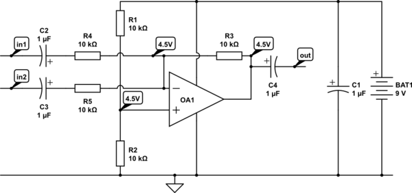
My circuit says plainly 1uF with the regular capacitor symbol. There is no plus-minus signs in the symbol, does this mean that I should not use an electrolytic capacitor?

If that is the case will any ceramic or polyester capacitor whitin specifications of voltage and Farad do the trick? How should I think about this?

schematic

simulate this circuit – Schematic created using CircuitLab

\$\endgroup\$
3

5 Answers 5

14
\$\begingroup\$

Since you said this is for audio, the answer is actually more tricky than you probably imagined. Electrically, you want a non-polarized capacitor, which means not electrolytic or tantalum in practise.

However, various types of capacitors have other tradeoffs that matter in audio applications. Multi-layer ceramics are nice in that they have good capacitance for the size and are not polarized. However, depending on the dielectric material, they can be quite non-linear and have another effect often called microphonics.

Microphonics is because the material exhibits a bit of the piezo effect. Vibrations will cause small voltage changes, which means the capacitor will act as a microphone. The effect is more subtle than piezo microphones deliberately designed for that purpose, but it can still be significant given the high signal to noise ratio of good audio.

The non-linearity is also a function of the dielectric material. A perfect capacitor will increase its voltage the same amount when a fixed charge is added no matter what the other conditions are. These non-linear dielectrics will have a different change in voltage for the same change of charge depending on the voltage. This is usually quantified as capacitance varying as a function of voltage. For example, a "10 µF 10 V" capacitor may act like 10 µF in the ±2 V region, but act more like a 5 µF capacitor to incremental change in the 8-10 V region. This non-linear response in audio circuits can cause harmonics that were not present in the original signal, which means distortion is added.

Ceramic dielectric types that start with "X" or "Y" in their name exhibit both these effects more than ceramic like "NP0". In a lot of applications, either effect doesn't matter, and the X and Y ceramics are useful because they give you more capacitance per volume. For audio applications it does matter, so you stick to the other types and realize that you won't be able to use the capacitors with the seemingly great capacitance and voltage combinations in the signal path. Heavily derating the voltage range also helps against dielectric non-linearity. For example, you might get a 20 V cap when the circuit guarantees the voltage accross it will always be within ±3 V.

Other dielectrics like mylar, polystyrene, and the like have less undesirable effect in the audio signal path, but also will have much lower capacitcances available and will be physically more bulky and probably more expensive.

Everything is a tradeoff.
\$\endgroup\$
5
  • \$\begingroup\$ Did you mention cost (and availability) in your answer? \$\endgroup\$
    – jippie
    Commented Mar 25, 2014 at 18:46
  • \$\begingroup\$ Because the capacitors are being used as high-pass filter elements, you can also play with the values a bit. Decrease C2-C4 to 0.1µF, and increase R3-R5 to 100 kohm to get the same filter with an easier to find capacitor. In this new range, you could use a thin-film cap (which would be much better than a ceramic for audio): industrial.panasonic.com/ww/i_e/21088/smd-film-capacitor_e/… \$\endgroup\$
    – sbell
    Commented Mar 25, 2014 at 19:53
  • 2
    \$\begingroup\$ @endolith: No, only one of them is, three others are not. Also, when I wrote this answer the schematic had not yet been posted and the OP only described something that sounded like it was meant to be unpolarized. \$\endgroup\$ Commented Mar 25, 2014 at 20:00
  • \$\begingroup\$ oh I misread the schematic \$\endgroup\$
    – endolith
    Commented Mar 25, 2014 at 20:08
  • \$\begingroup\$ Whoever downvoted this, it would be useful to explain what exactly you think is incorrect. \$\endgroup\$ Commented Mar 26, 2014 at 13:41
5
\$\begingroup\$

The input capacitors have +4.5V on the right hand side. Unless you're going for some extreme audiophile specs (in which case, the op-amp type matters a lot), you can use aluminum electrolytic capacitors connected with the + side to the right (input), or a non-polarized aluminum electrolytic. Somewhere around 1uF to 10uF is about right.

The output cap is the opposite (+4.5V on the left side).

I would increase the bypass capacitor across the battery to 100uF, they're not much bigger physically.

enter image description here

BTW, this circuit will make a reeely big thump when it is turned on.

\$\endgroup\$
4
\$\begingroup\$

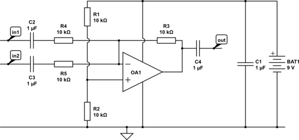
The capacitors are there because I didn't want to tire you with a symmetric power supply (plus and minus 5V), which adds extra complexity in the power supply.

Electrolytic caps are probably most cost effective and for will do fine for an experiment or a setup that doesn't require high end performance. Also availability is commonly pretty good. For a 9V power supply 16V capacitors will do fine.

schematic

simulate this circuit – Schematic created using CircuitLab

Spehro Pefhany is correct that at power on the loudspeaker will give a plop. Best to connect and power up this circuit before turning on the power amplifier.

\$\endgroup\$
2
\$\begingroup\$

Capacitors in series with a source are often (though not universally) going to see voltage in both directions. In this case (C2, C3, C4), they're a high-pass filter. You should definitely not use a polarized capacitor, like an electrolytic or a tantalum.

Capacitors in parallel with a DC source, it should be perfectly safe to use a polarized capacitor. C1, in this case.

\$\endgroup\$
0
1
\$\begingroup\$

You may assemble up a non polarized equivalent of an electrolythic capacitor by putting two capacitors in series, with polarities inverted between each other.

Example:

schematic

simulate this circuit – Schematic created using CircuitLab

This would solve the problem of not being told which polarity to use.

Two drawbacks:

  • putting two capacitors in series effectively halves the capacity seen from the "outside" of the two.

  • you might experience even more sound altering effects than those already covered by the posts above.

\$\endgroup\$

Your Answer

By clicking “Post Your Answer”, you agree to our terms of service and acknowledge you have read our privacy policy.

Not the answer you're looking for? Browse other questions tagged or ask your own question.