3
\$\begingroup\$

I am currently designing a narrow band pass filter at around 8Mhz, using the crystals having a resonance frequency of 8Mhz.

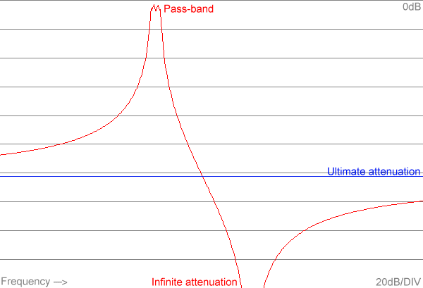
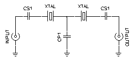
Using the tutorial from :http://www.giangrandi.ch/electronics/crystalfilters/xtalladder.html we manage to get a crystal ladder filter having a passband at around 8Mhz, bandwidth of 400Hz.

enter image description here

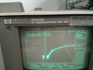
However, at high frequency (anything above 70Mhz), the filter response rise up and anything above 70Mhz can pass through. (see the picture)

enter image description here

We do see the response of the filter looks something like the picture below around 6~10Mhz. However, after the 70Mhz, the entire response is different. Is this normal?

How can we make a filter that ONLY pass through 8Mhz and not above 70Mhz?

we do see

\$\endgroup\$
2
  • \$\begingroup\$ my initial thought is that the signal is leaking through from either a physical capacitor OR a parasitic cap. You are definitely using ceramic caps right? \$\endgroup\$
    – hassan789
    Commented Mar 27, 2014 at 1:20
  • \$\begingroup\$ @hassan789, so you think this is not normal? and Yes, we got the ceramic caps, the cheap ones! \$\endgroup\$
    – kuku
    Commented Mar 27, 2014 at 1:28

2 Answers 2

8
\$\begingroup\$

This type of crystal lattice is not meant to be the only source of selectivity in a circuit. At very high frequencies, the parasitic capacitances of the crystal holders and electrodes simply pass everything.

It would be more typical for this sort of lattice to be incorporated into an IF chain that also has ordinary LC circuits to provide the required attenuation farther away from the desired passband.

Additional Detail:

The equivalent circuit for a quartz crystal is something like this:

schematic

simulate this circuit – Schematic created using CircuitLab

The components across the bottom represent the mechanical resonance of the crystal itself, while the capacitor at the top represents the capacitance of the electrodes and holder. Typical values are:

  • C_ser: 10s of fF (yes, femtofarads, 10-15F)
  • L: 10s of mH
  • R: 10s of ohms
  • C_par: 10s of pF

The crystal has a series-resonant frequency based on just C_ser and L. It has a relatively low impedance (basically just R) at this frequency.

It also has a parallel-resonant frequency when you consider the entire loop, including C_par. Since C_ser and C_par are essentially in series, together they have a slightly lower capacitance than C_ser alone, so the parallel-resonant frequency is slightly higher. The crystal's impedance is very high at this frequency.

But at frequencies much higher than either of the resonant frequencies, you can see that the impedance of C_par alone will dominate, and this just keeps decreasing with increasing frequency.
\$\endgroup\$
6
  • \$\begingroup\$ Thank you very much for your reply. Do you think replacing the capacitors will good ones will solve this problem? \$\endgroup\$
    – kuku
    Commented Mar 27, 2014 at 5:39
  • \$\begingroup\$ Also, do you think if we can make a passive bandpass filter (IF chain) using just capacitor and resistors? (more specifically, we just want to make a bpf with passband of 6 Mhz to 12 Mhz). I ask someone earlier in my lab today, they told me the passive bandpass filter doens't work at radio frequency, is this true? \$\endgroup\$
    – kuku
    Commented Mar 27, 2014 at 5:42
  • \$\begingroup\$ @user3222184: No, there's nothing wrong with the physical capacitors you have in your circuit. It's the stray (parasitic) capacitances of the crystals themselves that's causing your problem. \$\endgroup\$
    – Dave Tweed
    Commented Mar 27, 2014 at 11:17
  • \$\begingroup\$ @user3222184: A passive BPF made with resistors and capacitors only will be very lossy -- can you afford it in your signal budget? It's extremely difficult to build active filters in that range because it's difficult to get adequate gain (e.g., in an opamp), and again, parasitics can get in the way. What's wrong with using coils or transformers? \$\endgroup\$
    – Dave Tweed
    Commented Mar 27, 2014 at 11:21
  • 2
    \$\begingroup\$ Then all I can say is, "That's a crappy lab." Inductors are just as fundamental as resistors and capacitors, especially in RF work. \$\endgroup\$
    – Dave Tweed
    Commented Mar 27, 2014 at 15:44
1
\$\begingroup\$

Two ways are :

  1. augment the wideband attenuation with a separate (probably L-C) bandpass filter as described in Dave's answer.

  2. "Neutralise" (to use a 1920s term) the stray capacitance. It was normal to add a couple of extra turns on an RF transformer to generate a low amplitude signal of the opposite polarity to the wanted signal. This was then coupled to the output circuit via a low value trimmer capacitor to cancel out the stray : trimmer would be adjusted for maximum attenuation at the RHS of your analyser screen.

The second approach was patented as the "Neutrodyne" circuit and it can still be useful today.

\$\endgroup\$

Your Answer

By clicking “Post Your Answer”, you agree to our terms of service and acknowledge you have read our privacy policy.

Not the answer you're looking for? Browse other questions tagged or ask your own question.