1
\$\begingroup\$

schematic

simulate this circuit – Schematic created using CircuitLab
enter image description here

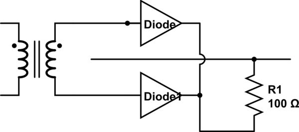
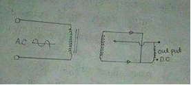
I have found this questions and the circuit seems worong to me because the output terminal hasn't end point.

If we add a more diode into the circuit will it be explainable? is the circuit has been drawn in a right way??

\$\endgroup\$

1 Answer 1

3
\$\begingroup\$

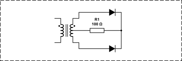
It would work if the transformer had a center tap and the unused wire was connected there.

schematic

simulate this circuit – Schematic created using CircuitLab

Now it is a full wave rectifier utilizing separate transformer windings wor each half wave. In the old days a transformer with a middle tap was cheaper than adding two extra diodes as used in a Graetz cell.

\$\endgroup\$
11
  • \$\begingroup\$ So the picture is not right. Now can I ask any question that, if we add more diodes then what would happen ? \$\endgroup\$
    – zero_field
    Commented Apr 26, 2014 at 8:19
  • \$\begingroup\$ Where would you want to use extra diodes? @zero_field \$\endgroup\$
    – jippie
    Commented Apr 26, 2014 at 8:20
  • \$\begingroup\$ Before resistor and before a diode also. what i think the extra diode will not affect any problem because the current due to positive polarity. And one more question, why the picture was wrong? i mean why do we need to connect as center tapped? \$\endgroup\$
    – zero_field
    Commented Apr 26, 2014 at 8:38
  • \$\begingroup\$ your picture is wrong because the resistor was only connected on one end, the other end has a loose wire. Can't follow you on the other part of your question. \$\endgroup\$
    – jippie
    Commented Apr 26, 2014 at 8:40
  • 1
    \$\begingroup\$ @VladimirCravero You sound like Tim the Toolman Taylor \$\endgroup\$
    – jippie
    Commented Apr 26, 2014 at 9:07

Your Answer

By clicking “Post Your Answer”, you agree to our terms of service and acknowledge you have read our privacy policy.

Not the answer you're looking for? Browse other questions tagged or ask your own question.