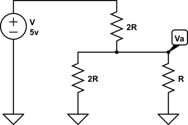
simulate this circuit – Schematic created using CircuitLab
Applying KCL: I get, (0-Va)/2R + (0-Va)/R = (5-Va) / 2R Is this right?
The resistor R is actually connected to GND, not drawn on the image.

simulate this circuit – Schematic created using CircuitLab
Applying KCL: I get, (0-Va)/2R + (0-Va)/R = (5-Va) / 2R Is this right?
The resistor R is actually connected to GND, not drawn on the image.
Whenever you see a node with resistors and, on the other end of the resistors, voltage values, then you can do what I discussed here. In this case, the answer would be:
$$\begin{align*} V_A&=\frac{0\:\textrm{V}\cdot\left(2\cdot R\right)\cdot \left(2\cdot R\right)+0\:\textrm{V}\cdot\left(2\cdot R\right)\cdot R+5\:\textrm{V}\cdot\left(2\cdot R\right)\cdot R}{\left(2\cdot R\right)\cdot \left(2\cdot R\right)+\left(2\cdot R\right)\cdot R+\left(2\cdot R\right)\cdot R}\\\\ &=\frac{10\cdot R^2}{8\cdot R^2}=\frac{5}{4}\:\textrm{V}=\underbrace{+1.25\:\textrm{V}}_\textrm{correct answer} \end{align*}$$
With nodal analysis, I look at currents as spilling outward and as spilling back inward, so I write this way:
$$\begin{align*}\frac{V_A}{2\cdot R}+\frac{V_A}{R}+\frac{V_A}{2\cdot R}&=\frac{0\:\textrm{V}}{2\cdot R}+\frac{0\:\textrm{V}}{R}+\frac{5\:\textrm{V}}{2\cdot R}\end{align*}$$
The currents spilling inward must equal the currents spilling outward. In the above equation the left side is the outward spilling currents and the right side is the inward spilling currents coming in from the node voltages on the other sides of the resistors.
Therefore:
$$\begin{align*}V_A\cdot\left(\frac{1}{2\cdot R}+\frac{1}{R}+\frac{1}{2\cdot R}\right)&=\frac{5\:\textrm{V}}{2\cdot R}\\\\ V_A&=\frac{\frac{5\:\textrm{V}}{2 R}}{\frac{1}{2 R}+\frac{1}{R}+\frac{1}{2 R}}\\\\ &=\frac{\frac{5\:\textrm{V}}{2 R}}{\frac{2}{R}}=\frac{5\:\textrm{V}}{2 R}\cdot \frac{R}{2} = \frac{5}{4}\:\textrm{V}=\underbrace{+1.25\:\textrm{V}}_\textrm{correct answer} \end{align*}$$
Your book is correct. If you solve your equation instead of the book's equation, you will get a wrong answer of \$V_A=-2.5\:\textrm{V}\$. There is no source for a negative voltage in your schematic. So you know it has to be wrong. You got the term right but just put it on the wrong side of the equation.