1
\$\begingroup\$

I have been looking over multiple designs for ideal diodes using FET transistors such as the circuits from these posts:

PMOSFET Ideal Diode for 24V

Understanding an 'ideal' diode made from a p-channel MOSFET and PNP transistors

and from this site:

http://jiggerjuice.info/electronics/projects/power/ideal-diode.html

The part that I don't understand is why they use so many other components in their designs. My question is if the following circuit I designed functions the same as the ones linked above.
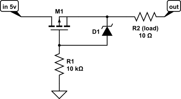
schematic

simulate this circuit – Schematic created using CircuitLab

The zener diode is being used to protect the gate terminal on the FET.

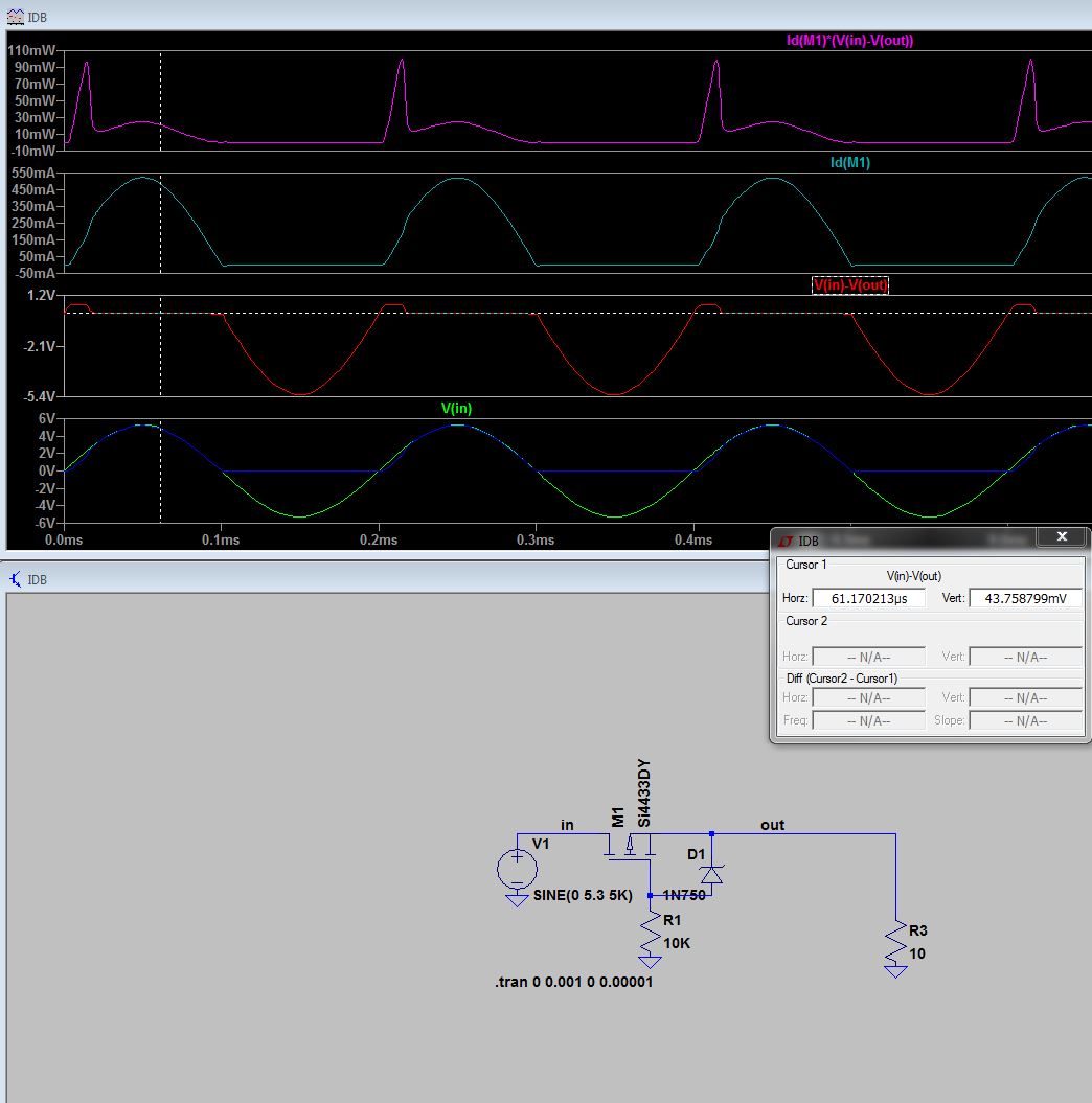
edit: for use as a high side half wave rectifier: Ideal Diode

\$\endgroup\$
1

1 Answer 1

1
\$\begingroup\$

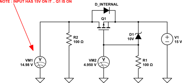
The whole point of an ideal diode is to detect and turn on when the output voltage is less than the input voltage.

All your circuit does is turn on the MOSFET when the voltage on the right is high enough.

In other words... your circuit is not even a non-ideal diode.

schematic

simulate this circuit – Schematic created using CircuitLab

The "other" components you mention form a comparator around the MOSFET and only turn it on if the left side voltage > right side voltage.

Your circuit could I guess be used for reverse polarity protection though assuming the voltage on the right has no, or a very short, residual after being unplugged on the left.

\$\endgroup\$
5
  • \$\begingroup\$ I suppose that I am confused as to the functionality of diodes? I was operating under the assumption that a diode allows current to pass through in one direction more or less unrestricted when a threshold voltage is reached and an ideal diode does this with minimum voltage drop across the diode. Could you help me understand what the key differences in functionality are between the two circuits? \$\endgroup\$
    – A Campbell
    Commented Oct 18, 2017 at 11:43
  • \$\begingroup\$ @ACampbell that's is only half of it though. It should still act as a diode, that is you want it to block current from going the other way. Your circuit does not do that. You may not be aware, MOSFETS conduct in either direction when on, so, in your circuit, when the right side is over Vgs the mosfet is just a turned on switch. \$\endgroup\$
    – Trevor_G
    Commented Oct 18, 2017 at 14:30
  • \$\begingroup\$ I figured out the difference: you are applying a positive voltage the other from the out. I have been using an AC voltage from the in terminal. I made edits accordingly \$\endgroup\$
    – A Campbell
    Commented Oct 19, 2017 at 18:31
  • \$\begingroup\$ @ACampbell it still is not a diode. \$\endgroup\$
    – Trevor_G
    Commented Oct 19, 2017 at 19:10
  • \$\begingroup\$ Do you need a ground reference at all? Why not just tie the source to the gate so that it will only conduct if the drain is at a lower voltage than the source? \$\endgroup\$ Commented Oct 16, 2018 at 22:44

Your Answer

By clicking “Post Your Answer”, you agree to our terms of service and acknowledge you have read our privacy policy.

Not the answer you're looking for? Browse other questions tagged or ask your own question.