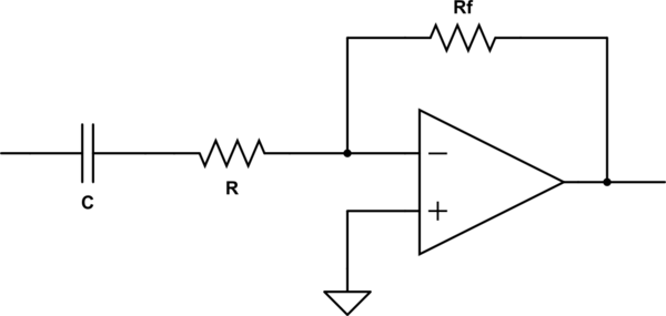
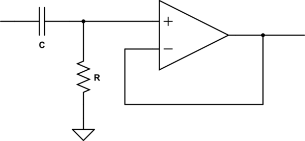
Both circuits appear the same to whatever is driving the input, and have the same high pass frequency rolloff. As you say, the main difference is that the first inverts while the second doesn't.
Even in a application like audio, for example, where you don't usually care about a inversion, there are practical differences between these two circuits.
The first circuit can be easily expanded to sum a number of signals. Each only needs its own impedance feeding into the inverting input of the opamp.
The second circuit is often used to exploit the very high input impedance of the opamp. In your case you used the same capacitor and resistor on the input, but this impedance could have been much higher in the second. That can be useful when dealing with high impedance signals that you don't want to load much. This circuit can also be configured for gain over 1 by adding a resistor divider in the feedback path.


