1
\$\begingroup\$

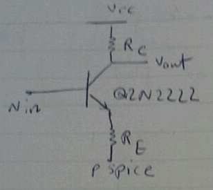
As always I have a rookie question. In a project, I need to analyze the circuit below in a way that the transistor would be in forward active mode. I need to calculate resistors and voltage sources, any combination would be acceptable as long as the transistor is in forward active. Then I need to apply a sinusoidal voltage to the input (base) and see the waveform of output (Vc). I have trouble using Pspice to do so. What type of analysis should I use? Can you walk me through it?

enter image description here

Also, considering there is no DC source connected to the base, how can it get into forward active, considering Vbe will always be negative?

\$\endgroup\$
6
  • \$\begingroup\$ Why do you think that Vbe "will always be negative"? Are you sure about this? Do you know how in most cases the required DC voltage at the base node is produced? Do you know the role of RE? \$\endgroup\$
    – LvW
    Commented Jun 12, 2014 at 15:53
  • \$\begingroup\$ In DC analysis I think the base would be connected to the ground and thus becomes zero...so anyway I look at it whatever Ie may be, Ve will be higher than zero... where am I mistaken? :D @LvW \$\endgroup\$
    – kasra5004
    Commented Jun 12, 2014 at 16:16
  • \$\begingroup\$ Walk before you can run - learn the basics first then when you are happy use spice. Spice is no substitute for sound background knowledge and, in my opinion, without that background knowledge, spice can be a disaster to the learning process and also give stupid results than a beginner might be inclined to believe. \$\endgroup\$
    – Andy aka
    Commented Jun 12, 2014 at 16:44
  • \$\begingroup\$ I know and I am doing it for one of my friends, I haven`t taken the course yet. would you be kind enough to explain where I am making the mistake? Is it possible to have the transistor in forward active without having a DC source connected to base? @Andyaka \$\endgroup\$
    – kasra5004
    Commented Jun 12, 2014 at 16:47
  • \$\begingroup\$ You need a positive bias voltage on the base with respect to the emitter but I'm not taking further newbie questions on how a transistor works or I might be here all day!! There are plenty of websites that can help. \$\endgroup\$
    – Andy aka
    Commented Jun 12, 2014 at 16:50

1 Answer 1

1
\$\begingroup\$

I am a beginner my self but I will try to answer your question. First some rules. For transistor to be in active mode of operation \$V_B - V_E = V_{BE}\$ must be larger then \$0.6V\$ and \$V_{CE}\$ must be larger then \$0.2V\$ and \$V_B < V_C\$.

I suppose that at your picture \$R_E\$ is grounded. Now think what happens when you apply sinusoidal signal that has amplitude of \$500mV\$. Transistor will not work \$500mV < 0.6V\$. Now suppose you increase amplitude to \$2V\$. What happens when signal is negative? \$V_B\$ is lower than ground and transistor will turn off. No current will flow to collector or from emitter. So you will get rectified sinusoidal signal.

The problems in you circuit is that transistor turns off when input signal if very small or negative. Two solutions. Connect negative supply to \$R_E\$ for example \$-V_{cc}\$. Or bias the base. Biasing the base means setting some positive dc voltage at it. You can do it using voltage divider.

So you must connect voltage divider output to base. The picture of the circuit can readily be found by searching for common emitter amplifier using google. You will see capacitor in those circuit. They are just used to remove the dc values from the signal so that the small signal will not affect biasing.
\$\endgroup\$
1
  • \$\begingroup\$ I like to add that the most important task of the input coupling capacitor is to prevent that the bias resistors are shorted by the signal source. \$\endgroup\$
    – LvW
    Commented Jun 13, 2014 at 12:54

Your Answer

By clicking “Post Your Answer”, you agree to our terms of service and acknowledge you have read our privacy policy.

Not the answer you're looking for? Browse other questions tagged or ask your own question.