1
\$\begingroup\$

I am having trouble calculating values for this audio amplifier. Input comes from AVR PWM operating at 44.1 kHz with high being at 3.3V. The speaker is 8 Ohm and speced for 1 Watt.

First two transistors, Q1 and Q2 provide high input impedance for PWM signal, while Q3 and Q4 form push-pull amplifier for the speaker. L1 and C1 form low pass filter, to convert PWM into analog signal.

First off, I am not enterely sure this is the best/correct approach, so if anyone has any better ideas let me know. The second thing is, I am not sure if I correctly calculated values for these resistors. These are the values I calculated earlier (R2, R3 = 47 Ohm, R1 = 330 Ohm, R6 = 470 Ohm, R5 = 1 kOhm, R4 = 470 Ohm).

I would really appreciate if with your anwser you could provide details and explanation of the calculations.

Also note, that AVR pin can source/sink maximum 20mA of current.
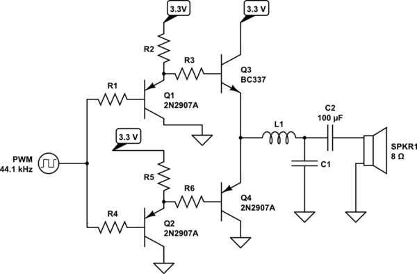
schematic

simulate this circuit – Schematic created using CircuitLab

Any help is greately appreciated!

\$\endgroup\$
1
  • \$\begingroup\$ I'd put the filter in front of the amplifier. \$\endgroup\$ Commented Jul 23, 2014 at 18:00

2 Answers 2

3
\$\begingroup\$

There is a bit of redundancy in your design - both Q1 and Q2 do exactly the same thing - you can get rid of one of them and have R3 and R6 connected to the same point such as the collector of Q1.

The other main problem is that the largest peak-to-peak voltage you'd be able to get on the output is about 1.5 volts because the output transistors are wired as emitter followers in push-pull - to make either transistor conduct, folk tend to use the 0.7 V base-emitter rule - i.e. the base needs to be 0.7 volts greater than the emitter (NPN) and 0.7 volts less than the emitter (PNP).

Given the speaker is 8 ohms and the biggest sinewave from the amp (on a 3V3 supply) is 0.53 volts RMS, the power into the speaker is 35 mW (before things start to clip/distort).

I'd throw it away and get a chip that does this sort of thing - even a H bridge amplifier suitable for motors is going to be better and you'll get a lot more power.

\$\endgroup\$
3
  • \$\begingroup\$ I was a bit skeptical myself, so tanks for clearing everything up. I was going to use LM386 or anyother IC for that matter, but its just that I dont have an easy access to electronical components, while I do have some transistors at home. \$\endgroup\$
    – Golaž
    Commented Jul 24, 2014 at 10:19
  • \$\begingroup\$ How did you come up with those calculations? What if I use 5V source? Or is there any other way? \$\endgroup\$
    – Golaž
    Commented Jul 24, 2014 at 10:31
  • \$\begingroup\$ The largest squarewave that can be produced is 3.3V - 1.8V p-p if driven hard - the 1.8V represents two base-emitter volt drops - this leaves 1.5 Vp-p \$\endgroup\$
    – Andy aka
    Commented Jul 24, 2014 at 11:49
1
\$\begingroup\$

First off you can't get 1 Watt of audio out of 3.3V into 8 ohms. Sure V^2/R is a bit bigger than 1, but it's PWM and off ~1/2 the time.

I tried to get my head around your circuit... and gave up. You've got a single ended (vs bipolar) input signal. (no?) So I don't think push pull is right. You just need some power gain, more current. Would it work if you just sent the input through R3 into Q3 and banged it on and off. Then the value of R3 doesn't matter too much. (you might make Q3 a fet, do they make 3.3 V fets?) The trick will be picking L1 and C1. I'm not sure about that, perhaps left as a exercise for you or SE. (I'll think too, if I define an impedance and a frequency....)

Oh if you want power in audio it becomes clear that you need higher voltage... or a transformer.

\$\endgroup\$

Your Answer

By clicking “Post Your Answer”, you agree to our terms of service and acknowledge you have read our privacy policy.

Not the answer you're looking for? Browse other questions tagged or ask your own question.