0
\$\begingroup\$

I'm trying to use a 12 volt WiFi relay setup to control a 12 volt DC motor. The WiFi relay has eight 10 A SPDT relays in it and the motor is 15 A. I understand how to wire it directly to the two relays that are in the box, but I'm lost after that. Here are my questions:

  1. Since I'm using two 10 A relays at the same time to control the motor (positive through one and ground through the other), does this mean that I have a 20 A capacity with the relays?

  2. How else could I wire this up to increase the relay capacity (or run the signals from the WiFi relays) to other relays and protect the WiFi relay box?

Here's the info on the WiFi relay:

http://download.carymart.com/0022001-y.pdf
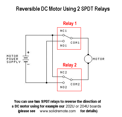
Here's the way I was going to wire it directly

\$\endgroup\$
3
  • 1
    \$\begingroup\$ In that circuit, the full motor current will flow through each relay, so your 10 Amp relays are not adequate to control your 15 Amp motor. \$\endgroup\$ Commented Sep 30, 2014 at 17:55
  • \$\begingroup\$ thats what I was thinking, but i figured i'd ask. \$\endgroup\$ Commented Sep 30, 2014 at 18:14
  • \$\begingroup\$ As Peter Bennett has said the relays are in SERIES in your schematic. PARALLEL would IN THEORY halve the current through each, but in reality they don't switch at the same time (biggest concern) and they don't have the same internal resistance (smaller concern). Edit: Looks like venny's answer has covered it all... \$\endgroup\$ Commented Mar 30, 2015 at 11:34

1 Answer 1

1
\$\begingroup\$
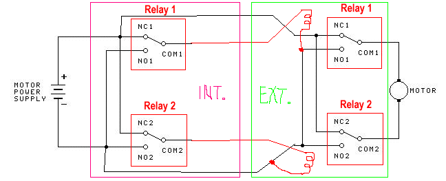
  1. Combining several relays in parallel is not good, because the contacts do not switch at exactly the same time, and it will cause arcing at the faster one. Another thing is that the motor is an inductive load and needs more current than the rated \$15\,\mathrm{A}\$ during startup.
  2. Without modifying the existing circuit, it can be done with another relay with 12V coil and contacts rated for inrush current of the motor.

Edit: Two 10A relays in series can still carry only 10A. Theoretically it should be possible to double the current by merging more relays to operate like one larger relay, but is not possible as described above.

Possible wiring can be done like this, for example with 30A or 40A automotive relays:

pic

\$\endgroup\$
2
  • \$\begingroup\$ ok, thanks for the answer. So what do I need and how should I wire it up? \$\endgroup\$ Commented Sep 30, 2014 at 18:04
  • \$\begingroup\$ Thanks Venny. So i'll be running the relays in parallel as pictured above so they'll share the load. Im assuming i'll need to use a 5 pin SPDT relay, but im having a hard time following the voltage flow thru the relays and understanding the red output from the internal relays. Are you using the red wires as trigger wires for the second relays? It looks like the wiring already has a completed loop (pos from relay 1 in its natural position and neg from the input wire) in this diagram. Is that the way it should be? or is that red wire supposed to be just the signal wire to the other ext coil? \$\endgroup\$ Commented Sep 30, 2014 at 20:31

Your Answer

By clicking “Post Your Answer”, you agree to our terms of service and acknowledge you have read our privacy policy.

Not the answer you're looking for? Browse other questions tagged or ask your own question.