0
\$\begingroup\$

I'm having trouble switching an AC motor. Relays spark and glue contacts, and SSRs start to flicker and not pass the full input after a while.

The motor has 3 terminals for 230VAC mains. One is common, one is UP, and the last one is DOWN. common and one of the other ones has to be connected to mains for the motor to move.

The SSRs I tried are rated for 2A 240VAC (FINDER 34.81-8240), use a triac (So inductive kickback should not be a problem), and have zero-crossing turn-on (So inrush current from the motor and it's kickstart capacitor should not matter)

Having ran out of ideas, I tried to switch the SSRs to mechanical relays (rated 8A). Unfortunatelly, they seemed to get stuck after a while. I could see no sparking on closing of the relay, but a massive spark when opening it. (Sometimes, I guess it depended on the phase of current).

So I tried putting 2 RC snubbers (120Ohm, 0.1uF), across UP-common and DOWN-common, parrarel to the motor (To protect two relays), but that didn't seem to change the sparks at all.

I cannot use a bigger relay and would rather not use any unstable components like MOVs, as this setup resides inside walls. I thought of zero-cross current detection for opening the mechanical relays, but apparently they are too slow.

How can I protect the relays/SSRs so that they don't fail?

EDIT: I should also propably mention, that the relays are controlled directly from a PLC's digital output module (Unitronics IO-TO16) connected to A2 on each SSR/relay. The only relevant part of the program, esures that they are never on at the same time. (Though, I didn't really see any damage with stuck relays in such condition). Also, I had some other SSRs, which failed differently. Some would start flickering, but more interestingly, some would work normally themselves, but cause SSRs AND relays NEXT TO them to flicker, as long as they had mains connected to one terminal.
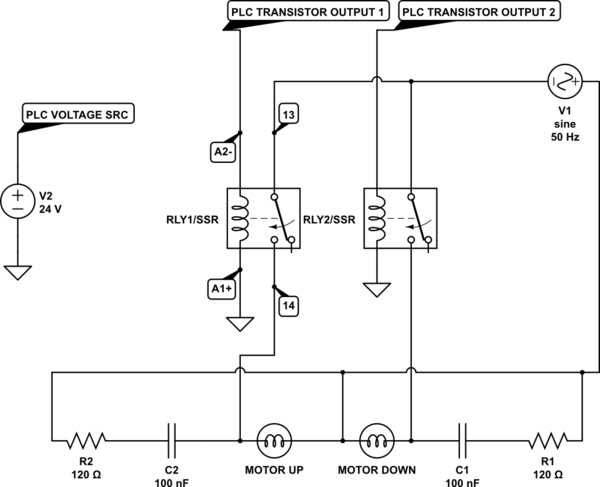
schematic

simulate this circuit – Schematic created using CircuitLab

\$\endgroup\$
3
  • 1
    \$\begingroup\$ Let's see your circuit schematic and give us some assurance that you're not switching from forward to reverse without a brief off-time. There's an schematic button on the editor toolbar. Use the bulb symbol for your motor coils. Double-click to edit parameters. R to rotate. V and H to flip. \$\endgroup\$
    – Transistor
    Commented Nov 20, 2018 at 22:22
  • \$\begingroup\$ Your use of a snubber is good, but try putting it across the relay contacts, rather than the motor winding. In addition, there should be short pause between opening of one relay and closing of the other, so that current does not flow in both windings simultaneously. \$\endgroup\$ Commented Nov 21, 2018 at 1:45
  • \$\begingroup\$ I can add a delay inside the PLC program, currently if RL1 is on and I request RL2 to turn on, RL1 is turned off and RL2 is turned on in same program cycle (couple microsecs). To be fair though, I didn't really use the covers like that. Usually it was like MOTORup for 50 secs -> off for 8 hours -> MOTORdown for 50secs \$\endgroup\$
    – M. S.
    Commented Nov 21, 2018 at 21:53

2 Answers 2

1
\$\begingroup\$

schematic

simulate this circuit – Schematic created using CircuitLab
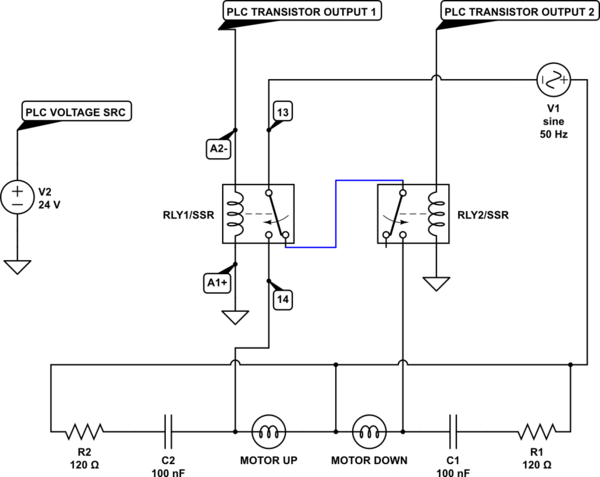
Figure 1. Modified hardware interlock.

Just a suggestion but I would also add a hard-wired interlock on the relay wiring. This protects you in the event of a PLC malfunction.

\$\endgroup\$
1
  • \$\begingroup\$ Thanks, but the reason I didn't do that was that the SSRs unlike relays, don't have on-by-default output, and I wanted to be able to use both. Besides, even if something fails and both outputs are on, whatever circuitry the motor unit has in it, doesn't seem to get damaged. It only buzzez a bit. Ironically, the switching back-and-forth between relays and SSRs was what caused me to not notice the polarity mismatch I described in my answer. I still don't really understand why the SSRs worked at all. \$\endgroup\$
    – M. S.
    Commented Nov 21, 2018 at 21:44
0
\$\begingroup\$

Well, I think I figured it out...

Apparently the person who wired the relay slots, didn't use the standard pinout. So like in my schematic, A1+ was GND and A2- was switched +24VDC. Of course this didn't matter for relays which were originally installed, but it did matter for SSRs which place an LED there. I'm kind of surprised that SSRs worked in this config for like 4 months, or even that they switched at all, considering diodes should't pass in reverse. So I'm not actually sure if this was what damaged them, or if there is a rectifier inside the SSRs and it was something totally different. For now, I switched them to the proper polarity. I will see if the new ones will also fail in some time.

As for the mechanical relays, I think that the snubber was just too small. I found some Omron spec, which recommends ~1uF per 1A (If you don't know anything more about the motor and it's coils). And this was a 200W motor. I tried putting a bunch of snubbers in pararell and that seemed to make the arc dimmer. I left the 120Ohm/0.1uF snubber as is, and use it with SSRs, hoping if will reduce the effect of any random motor fluctuations.

\$\endgroup\$

Your Answer

By clicking “Post Your Answer”, you agree to our terms of service and acknowledge you have read our privacy policy.

Not the answer you're looking for? Browse other questions tagged or ask your own question.