1
\$\begingroup\$

This circuit was designed to save electronic components in the assembled board from damage. It gives warning beep if there is a short circuit in the assembled board.

Thus it helps to switch off the power supply immediately to save valuable components. If the circuit board is OK, Green LED lights indicating that power supply is normal. If there is a short in the PCB tracks or pins of components, Green LED turns off and Buzzer sounds indicating the short circuit.

The circuit uses two NPN transistors BC 547 to sense the short circuit. If the assembled board is normal, current flows from the power supply through polarity protecting diode D2. The Assembled board gets power and Green LED lights.

At the same time Q2 forward bias and its collector goes to ground potential. This makes Q1 off due the absence of base bias. Buzzer and Red LED connected to the collector of Q1 remains off. If there is a short circuit in the board under test, D4 reverse biases and Q2 turns off. Now the base of Q1 becomes high and it conducts. This turns on Buzzer and Red LED to indicate short circuit.

Now, I'm using general purpose components here, what I want its to make this circuit "universal", or at least usable for currents up to 10 Amps, I have some questions,

  1. Would this circuit be able to replace slow blow fuses up to 10 Amperes?

  2. How can I adapt this circuit for negative voltages?

  3. Adding 1mH choke inductors right after D2 could help me out to stop transients from destroying my circuit in a worst case scenario?

Any feedback about how can I improve this is welcome
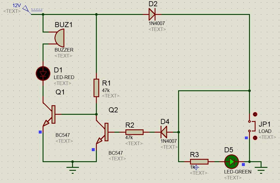
Circuit

\$\endgroup\$

4 Answers 4

3
\$\begingroup\$

Very nice circuit!

To answer your questions:

  1. This circuit is not able to replace a fuse, because it does not protect in case of a short circuit, it only gives a warning. Your diode D2 still needs to handle a forward voltage of 12V in case of a short circuit and will break as a result. As a solution to this, you could think of a circuit that turns of your power supply to the load, whenever the load is short circuit. Or maybe even safer. A circuit with memory, that turns off the power supply when the load is short circuit and until a button is pushed stays off.
  2. To adapt this circuit for a negative power supply, you could connecto the 0V to the location of your current 12V and the -12V connection to your current GND connection. You might however want to have the diode not in the GND connection, and move it in the path of the -12V supply. In that case your diode D2 would forward from D5 and JP1 to your -12V supply, and you could leave out the inverter made with Q2 and R1.
  3. What kind of transients do you mean here? Short over voltage of your 12V power supply?
\$\endgroup\$
2
  • \$\begingroup\$ I suspect that, in practice, D2 is the fuse in this circuit. \$\endgroup\$
    – Simon B
    Commented Oct 9, 2017 at 23:06
  • \$\begingroup\$ The whole point of a fuse is that it can safely break. The diode could catch fire on a short circuit and should therefore definitely not be used as a fuse. \$\endgroup\$
    – Douwe66
    Commented Oct 10, 2017 at 7:00
2
\$\begingroup\$

I see a couple of problems with your circuit:

  1. Without a current limiter somewhere, D2 must be able to handle the full short-circuit current of the power supply. Even with a current limiter, D2 must be able to handle the normal current required by the load (and then the current limiter must be adjusted to pass the normal load current).

  2. While some short circuits will cause excessive power supply current, which could be detected with this circuit, many faults ocurring during manufacture result in shorts between signal lines, or otherwise cause faulty operation without causing excessive power supply current.

\$\endgroup\$
1
  • 1
    \$\begingroup\$ A third problem : if the short circuit is at the end of a long wire, it may draw excessive currents and pull D4 down to say 6V or 3V, which are still high enough to prevent the alarm sounding. Definitely not a fuse replacement. \$\endgroup\$
    – user16324
    Commented Nov 15, 2014 at 10:13
2
\$\begingroup\$

If it's a short circuit, won't that pull the power supply down near zero... nothing turns on!? (Have you tested this circuit with different power supplies?) When powering up a circuit for the first time (that may have shorts) I like to use a current limited supply. (Sometimes that's one with a changeable max current, but other times it's just a wimpy supply that can't source too much current.

\$\endgroup\$
2
\$\begingroup\$

(This doesn't really answer your question, but I think its relevant to other readers...)

You can get electronic fuses that are designed for this purpose. For example, the TPS25921.

Devices such as that have traditional current limiting circuits, but with integrated thermal protection. On a short, the resulting behaviour is that they can 'test' the line repeatedly until the fault is cleared while keeping the current below the design current, making them suitable fuse replacements.

In addition, the more advanced ones like the TPS25921 will feature over and under-voltage protection for transients (though you then need to protect the IC itself from them when it switches!), and fault indicators (for your LEDs).

The TPS25921 is not rated for 10A, but there are many variants. I'd guess they'd be roughly double or triple the cost of the components you'd replace in your diagram, but compared to the time to implement, debug, PCB space saved, etc, probably still be quite economical.

\$\endgroup\$

Your Answer

By clicking “Post Your Answer”, you agree to our terms of service and acknowledge you have read our privacy policy.

Not the answer you're looking for? Browse other questions tagged or ask your own question.