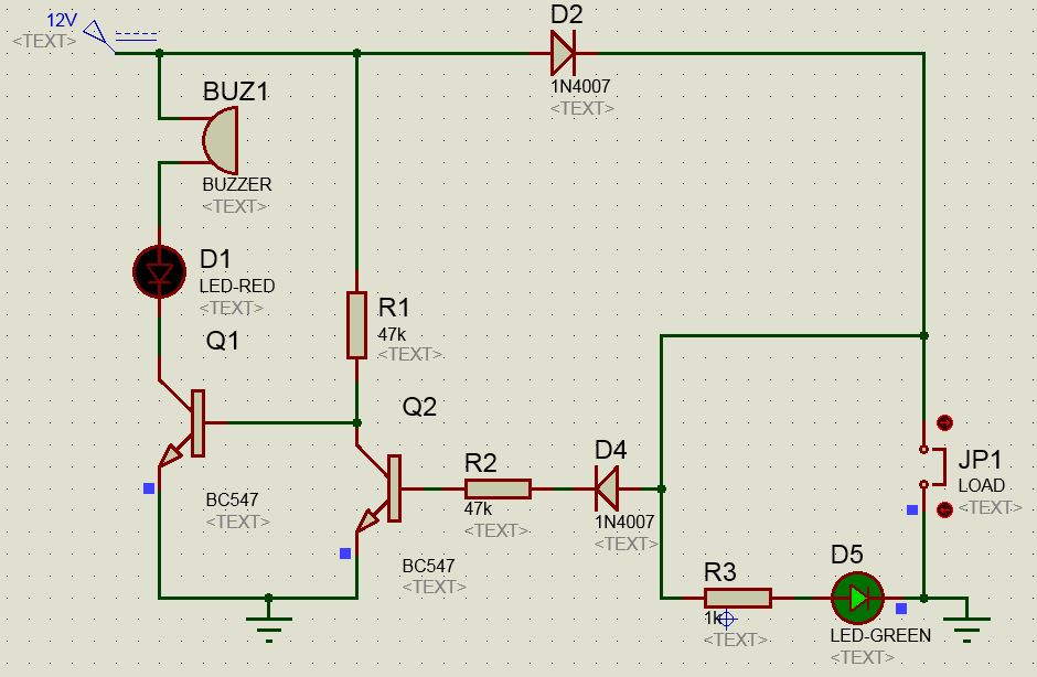
This circuit was designed to save electronic components in the assembled board from damage. It gives warning beep if there is a short circuit in the assembled board.
Thus it helps to switch off the power supply immediately to save valuable components. If the circuit board is OK, Green LED lights indicating that power supply is normal. If there is a short in the PCB tracks or pins of components, Green LED turns off and Buzzer sounds indicating the short circuit.
The circuit uses two NPN transistors BC 547 to sense the short circuit. If the assembled board is normal, current flows from the power supply through polarity protecting diode D2. The Assembled board gets power and Green LED lights.
At the same time Q2 forward bias and its collector goes to ground potential. This makes Q1 off due the absence of base bias. Buzzer and Red LED connected to the collector of Q1 remains off. If there is a short circuit in the board under test, D4 reverse biases and Q2 turns off. Now the base of Q1 becomes high and it conducts. This turns on Buzzer and Red LED to indicate short circuit.
Now, I'm using general purpose components here, what I want its to make this circuit "universal", or at least usable for currents up to 10 Amps, I have some questions,
Would this circuit be able to replace slow blow fuses up to 10 Amperes?
How can I adapt this circuit for negative voltages?
Adding 1mH choke inductors right after D2 could help me out to stop transients from destroying my circuit in a worst case scenario?
Any feedback about how can I improve this is welcome

