0
\$\begingroup\$

Many switch mode buck LED drivers use a current mode scheme with a sense resistor back to a Vsens or Current Sense input on the chip. A good example is the LM3404. Here's the typical use circuit:
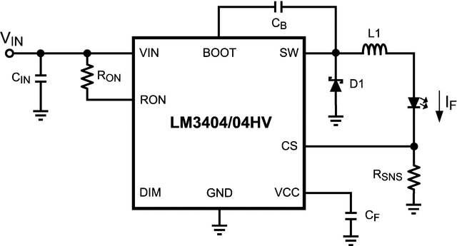
enter image description here

I am wondering can I tweak the driver, for calibration purposes, by altering the voltage going in a the CS input. I realise I can PWM drive this device via the DIM input but, if the purpose is one off calibration, then this is extra effort for nothing. The reason is that we have an expensive UV LED emitter that runs nominally at 700mA, but may need to be brought down to 500mA for calibration of a UV receive sensor. Changing Rsns is a nuisance and a variable Rsns isn't really reasonable.

If I set up for 500mA, then pulling CS down to ground a little should allow me to raise If by a proportionate amount:
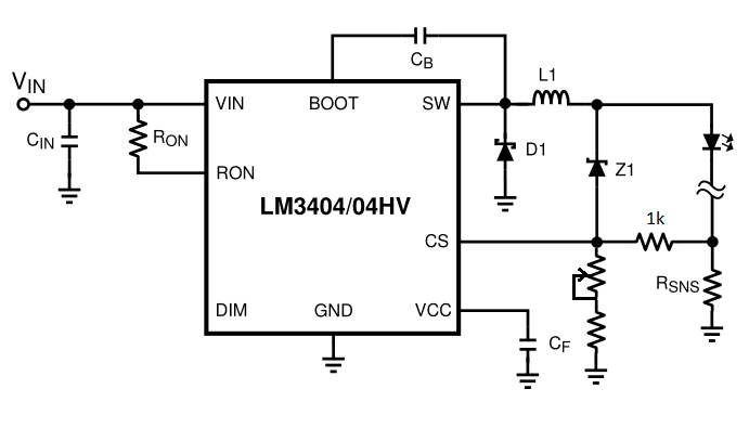
enter image description here

I've taken the "circuit with overvoltage protection" example from the datasheet - thus the zener - and added a pulldown. I've done it in the way I have so that if the wiper doesn't connect for some reason, the current doesn't jump up (it would if the wiper went directly to CS).

This looks ok but with SMPS feedback systems I'm never sure. Should there be a bypass cap around the 1K resistor to couple voltage ripple to the LM3404's CS pin (seems necessary for operation of its COT system)?

Edit: Just as I posted this I found this interesting link which does it the other way - takes the Vcc output from the LM3404 and pulls upward. Doesn't seem too precise though as the Vcc pin is quite variable.

Edit: and the AL8805 allows analog dimming on its dim input. Still, I'd be very interested in if this mod is a reasonable one.

\$\endgroup\$

1 Answer 1

2
\$\begingroup\$

Basically you are putting a pot in parallel with Rsns in order to "allow" two current settings. Why don't you use a fixed resistor and a 0.1" jumper. Normally the jumper would be in place for the higher current thru the LED then you remove the jumper to activate the lower current feed. I also don't like pots much and would much rather use a resistor and jumper especially if the two settings are known and fixed.

\$\endgroup\$
3
  • \$\begingroup\$ I get your meaning - If I wanted 500 or 600mA then that would be fine. But I figure the calibration might just be fine LED output adjustments though - say between 600-650mA. That's awkward to do with large currents and small Rsens. \$\endgroup\$
    – carveone
    Commented Dec 6, 2014 at 17:54
  • \$\begingroup\$ I guess the right thing to do is use a bench supply, decide what current you want and then ask me to output the right current instead of "not quite right - we need it slightly brighter". I'm trying to put the problem back to the people doing the calibration :-) \$\endgroup\$
    – carveone
    Commented Dec 6, 2014 at 18:02
  • \$\begingroup\$ Actually I think this is a better solution than taking a percentage of Vsens, even though it's more "quantised" if you will. Mainly because pulling Vsens down like this puts more current through Rsens which has to be made larger for the smaller initial current. Setting initial to 200mA would require Rsens = 1 ohm (CS ref is 200mV). So making that 1 amp would burn 1W in Rsens. Which is really inefficient. The link I referred to is the better way of "analog dimming". But I'll use the AL8805 anyway! \$\endgroup\$
    – carveone
    Commented Dec 9, 2014 at 18:37

Your Answer

By clicking “Post Your Answer”, you agree to our terms of service and acknowledge you have read our privacy policy.

Not the answer you're looking for? Browse other questions tagged or ask your own question.