0
\$\begingroup\$

I'm designing a 16 x 32 RGB LED Matrix and its controller / driver board. So I've designed a couple of solution approaches and I'm wondering if there is a better way to drive multiple 4 to 16 line decoders ( I am using the CD4514B ) than the solution I'll show in the image below.


Some background information:

Simply I want to use two of the 4-16 decoders to end up with 32 channels so I can select/enable ONE row|column of the matrix at a time.

The other row|column ( the 16 pin side of the matrix in this solution ) is selected/activeted by two 8bit shift registers ( times three since RGB ).

At this point I'm not sure if I should control the 16pin side by 2x shift registers and the 32pin side by 2x 16bit decoders OR control the 16pin side by 1x 16bit decoder and the 32pin side by 4x 8bit shift registers.

I am also not shure if I should/can split the matrix into 8 individual 8x8 matrixes, and why I should do that...

Since I dont even know which AVR I'll be using as the main unit at this point, I don't know how many IO pins I can use. Even if I want to keep the size and costs as down as possible, I dont want to run into some timing / speed problems. And that is the point - I dont know which design suits the best, because I will need many shift registers in a tree-like-structure when I want to use a small AVR like the ATtiny45 ( 5 IO pins ).

So If you have some ideas / experiences about this, please tell me.


But to come back to the original question, here is my thought about the dual 4-16 decoders:
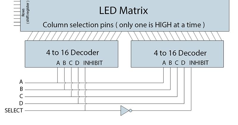
enter image description here

What do you think about it ? Is this the common way to do this ?

For sure, for chaining more than 2 decoders, I could simply use another ( e.g. 3 to 8 bit ) decoder, just to control the inhibits, but for this one I'm dealing with only two.

Thank you for your help.

\$\endgroup\$

2 Answers 2

1
\$\begingroup\$

That's exactly the way it's done, as long as you don't want to turn off all the LEDs at any time. If so

schematic

simulate this circuit – Schematic created using CircuitLab

will allow a master inhibit to override the select line.

\$\endgroup\$
2
  • \$\begingroup\$ Thank you for that addition of the master inhibit, but I don't think that I need that functionality ( yet ). Do you also agree with my row/col - shiftregister/decoder alignment ? would It make a big diference in timing and component size/amount if I would swap the sides or split the matrix in to individual ones ? \$\endgroup\$
    – Ace
    Commented Jan 7, 2015 at 15:35
  • \$\begingroup\$ I think your last possibility, dividing the matrix into 8 x 8 submatrices is the way to go. Michael Karas is right that trying for too large a multiplexing factor will give you problems with drive levels. You have presumably studied the 4514 data sheet ti.com/lit/ds/symlink/cd4514b.pdf Note that the maximum current you can get from any particular output is ~ 1 mA. With a 32:1 multiplexer setup, the maximum average current you can get for any LED is about 30 uA, and you won't like that. Whatever you do, you'll need high-current drivers instead of using the outputs directly. \$\endgroup\$ Commented Jan 7, 2015 at 17:46
0
\$\begingroup\$

The degree to which you choose to matrix the LEDs has to have more consideration than just the minimum complement of I/O pins needed. You also need to consider the duty cycle of each LED. With your proposed dual 4-16 decoders you will only have a 1/32 duty cycle of the LEDs in each column. This can have a serious impact on how bright you can get the LEDs to light. As a minimum you end up having to boost the peak current into the LEDs to a quite high level.

My experience is that you would have a lot better success with a duty cycle of 1/8 or greater.

\$\endgroup\$
2
  • \$\begingroup\$ How could I get a duty cycle of 1/8 and what would be the best solution for driving a 16x32 rgb led matrix ? I don't know, but does it matters, that I was planing to calculate the duty cycle within the AVR and set the clock and the data based on that. So I can have a column active as long as I want/need to. \$\endgroup\$
    – Ace
    Commented Jan 7, 2015 at 15:30
  • \$\begingroup\$ Bottom line is that unless you latch the drive at each LED then extending the time on for each column (with only one column at a time) it will not change the duty cycle - just reduces the frequency. You get 1/8 duty cycle by limiting the number of columns that are singularly on to just one out of eight. It may be possible to divide up your matrix into two each with 8 columns that you operate in parallel. Such parallel matrices could share common row drivers of the circuitry is built correctly so that the row drivers can handle the current of two columns at once. \$\endgroup\$ Commented Jan 7, 2015 at 16:40

Your Answer

By clicking “Post Your Answer”, you agree to our terms of service and acknowledge you have read our privacy policy.

Not the answer you're looking for? Browse other questions tagged or ask your own question.